Non-Contact AC Mains Voltage Detector
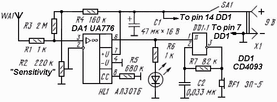
The circuit diagram of the non-contact voltage detector is illustrated in Figure 1. It consists of two main components: an AC amplifier and an audio oscillator, which is based on the Schmitt trigger DD1.1 of the IC CD4093, along with the resistor-capacitor network R7C2 that determines the frequency of the audio signal generated by the piezoelectric buzzer BF1. When the antenna WA1 is positioned near a power supply, the interference at 50 or 60 Hz is amplified by IC DA1, resulting in the illumination of the LED HL1. The output voltage from the operational amplifier also activates the audio generator. The device consumes no more than 2 mA when powered by a 9V battery, and the current consumption increases to 6.7 mA when the LED is illuminated. Disconnecting the LED while using only the audio generator reduces the current consumption. The printed circuit board (PCB) is housed in a suitable plastic enclosure, with the antenna positioned away from the operator's hands. The switch SA1, LED HL1, and piezoelectric buzzer BF1 are mounted on the front panel. The device's sensitivity is adjustable via the potentiometer R2. For smoother adjustment, the 220K potentiometer R2 can be replaced with a 22K potentiometer in conjunction with a 200K resistor connected between the lower pin and ground.
The non-contact voltage detector circuit is designed to sense alternating current (AC) voltage without direct electrical contact. The AC amplifier stage is critical for detecting the low-level voltage induced by nearby AC sources. The Schmitt trigger configuration in the audio oscillator provides a stable output frequency that is less susceptible to noise, ensuring reliable activation of the piezoelectric buzzer BF1. The choice of the CD4093 IC allows for low power consumption while maintaining performance, making it ideal for battery-operated devices.
The antenna WA1 plays a crucial role in capturing the electromagnetic fields generated by AC power lines, and its placement is essential for optimal sensitivity. The design ensures that the operator remains safe by requiring the antenna to be kept at a distance from the user's hands. The audio output, generated by the piezoelectric buzzer, serves as an audible alert to the presence of voltage, enhancing user awareness in potentially hazardous situations.
The current consumption characteristics are noteworthy; the device operates efficiently at low power, making it suitable for portable applications. The flexibility in adjusting sensitivity through potentiometer R2 allows users to tailor the detector's response based on environmental conditions or specific applications. Replacing R2 with a lower value potentiometer and an additional resistor can fine-tune sensitivity for more precise detection, accommodating various operational scenarios.
The overall design, including the PCB layout and the housing, emphasizes durability and usability. The components are arranged to facilitate easy access to the switch, LED, and buzzer, ensuring that users can quickly and effectively operate the device. This non-contact voltage detector is an essential tool for electricians and technicians, providing a safe and efficient method for identifying live electrical circuits.The circuit diagram of the non-contact voltage detector is shown on the figure 1. It consist of two parts - the AC amplifier and the audio oscillator, based on the Schmitt trigger DD1. 1 of IC CD4093 with the network R7C2, which determines the frequency of the audio signal, generated by piezoelectric buzzer BF1.
When the antenna WA1 is located near a power supply, the interference of 50 or 60 Hz is amplified by IC DA1 and as a result the LED HL1 will illuminate. The same output voltage of the op amp starts audio generator. The current consumption of the device is no more than 2 mA when using 9V battery, and current consumption goes up to 6.
7 mA when the LED lights up. If disconnect the LED and use only audio generator then it reduces current consumption. The PCB is enclosed in a suitable plastic box, the antenna must be as far as possible from a hands. The switch SA1, LED HL1 and piezoelectric buzzer BF1 is mounted on the front panel. The sensitivity of the device is adjusted by the potentiometer R2 To make it smoother the potentiometer R2 220K can be replaced with another one of 22K and a resistor of 200K, connected between the lower pin and the ground. 🔗 External reference
