
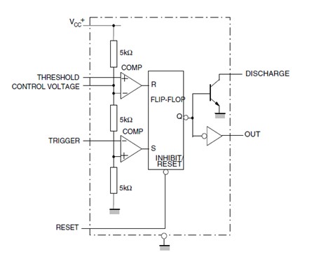
Non-standard 555 Astable Multivibrator

The schematic for this square wave generator can be designed using a 555 timer in a modified astable configuration to achieve a 50% duty cycle. The circuit will include the 555 timer IC, a timing capacitor (C1), and two timing resistors (R1 and R2). The values of R1 and R2 must be selected such that their ratio maintains the duty cycle at 50%, which can be achieved by setting R1 equal to R2. The control pin (pin 5) will be connected to ground through a 0.1 µF capacitor for stability.
To create the triangle wave, the output from the 555 timer (pin 3) will be fed into an integrator circuit composed of an operational amplifier configured with a feedback capacitor (C2) and a resistor (R3) to set the time constant. The output of the integrator will then be connected to a comparator circuit, which will allow for independent duty cycle adjustment.
The output from the comparator can be used to drive an LED or other load. A current-limiting resistor (R4) should be placed in series with the LED to prevent excessive current draw from the output of the 555 timer. An operational amplifier can also be included as a buffer to isolate the LED from the timing circuit, ensuring that the timing capacitor charges and discharges correctly without being affected by the LED load.
For troubleshooting, it is crucial to monitor the voltage across the timing capacitor at pins 2 and 6, observing the expected sawtooth waveform. Any discrepancies in the charge and discharge times may indicate issues with component values or connections. The use of a CMOS version of the 555 timer is recommended for improved performance, particularly in applications requiring precise timing and consistent output levels. Adjustments to the resistor values and capacitor types may be necessary to achieve the desired frequency and duty cycle characteristics.I need to make a square-wave with variable frequency, but 50% duty cycle. The 555 timer seemed like a good idea, but with the normal astable multivibrator circuit you see everywhere, changing the frequency always ends up changing the duty cycle a bit. However, In my 20 year old "IC 555 Projects" book I found a circuit which i t specifically states has a variable frequency but 50% duty cycle. Not shown on the diagram is my decoupling of the power rails, and my decoupling of pin 5 (the control pin) to ground with a 0. 1uf capacitor (this is often recommended if you are not using it). The ultimate plan is a stroboscope that can go well into audio frequencies with one pot controlling frequency and another controlling duty cycle.
I will send the square wave from the 555 through an integrator, producing a triangle wave, then stick that through a comparator so I can vary the duty cycle completely independently of the frequency (which doesn`t seem possible with the 555 by itself). You can further investigate what is happening by probing the voltage on the capacitor, at pins 2 & 6.
You should see a sawtooth moving between 1/3 and 2/3 of the supply voltage. (Make sure the capacitor value is large enough that the probe capacitance does not distort the circuit. ) You may also have a problem with the LED loading the output down too much. Remember the output is providing current to charge up the timing capacitor, and if you make it also drive the LED you might overburden it.
Put a high value resistor in series with the LED to limit the current, or put a high impedance buffer like an op amp between the 555 and the LED. However, from the scope trace, it comes out as about 6 KHz. The timebase is 50us, and the period of the waveform is about 3. 2 divisions 1/(3. 2* 50x10-6) = 6250 Hz. Clearly you have a problem with the operation of the circuit as the capacitor is taking much longer to charge up than to discharge.
We need to ask why that might be I don`t immediately know, but something is clearly wrong there. What is the supply voltage to the circuit Also what is the voltage scale on the various traces Is the output pin voltage changing between 0 and Vcc as you would expect Try using the CMOS version of the 555. It has the advantage of a rail to rail output at low currents, and at least has equal source and sink capability.
Otherwise use a 10k or higher resistor and connect it to pin 7 instead of 3, and use a 470R to 1k resistor from 7 to the supply. That should help with loading. The big problem with the bipolar 555 is the high output voltage is not well defined, being rather load dependent.
Sink is a beefy transistor for both pin 3 and 7 ( they are the same size transistor on the die and are driven the same) so you definitely need some active pull up to the circuit. Better is to have the load be switched to ground rather than source current. Clearly you have a problem with the operation of the circuit as the capacitor is taking much longer to charge up than to discharge.
We need to ask why that might be I don`t immediately know, but something is clearly wrong there. What is the supply voltage to the circuit Also what is the voltage scale on the various traces Is the output pin voltage changing between 0 and Vcc as you would expect The vertical scale on all those pictures is 0. 2V/Div, but accounting for the x10 probes I`m using, it`s 2V/Div. The trace is slightly too high in those pics. I`m supplying 5V to the circuit and the output pin is going between 0 and 3. 6V. The Capacitor charge seems to be going from 1. 8V to 3. 5V. Since the capacitor is supposed to be charging and discharging through the same resistor, it`s odd that the times are different.
I`ve just changed the capacitor to an "identical" ceramic disc capacitor, and realized that the one I was using was 65. 1nf which is 38% off from its stated value of 473nf 🔗 External reference
Related Circuits
A low power H-bridge may be necessary for driving a motor. The 555 integrated circuit (IC) can handle a load of up to 200 mA, either sourcing or sinking, making it a potential driver if the output can be...
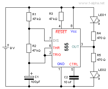
The NE555 can be used to construct an astable multivibrator or blinker. It is important to understand the necessary components and considerations involved in this process. The NE555 timer IC is a versatile device commonly used in various timing, pulse...
A circuit utilizing a standard digital quartz electronic watch, with its crystal soldered, forms a digital frequency meter as illustrated by the connected circuit. The test signal is applied to the E and F sides via components such as...
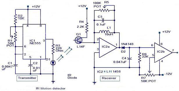
The following circuit illustrates an Infrared Motion Sensor circuit diagram. Features include the use of the NE555 integrated circuit, with a detection zone coverage of 80 degrees. The Infrared Motion Sensor circuit utilizes the NE555 timer IC configured in a...
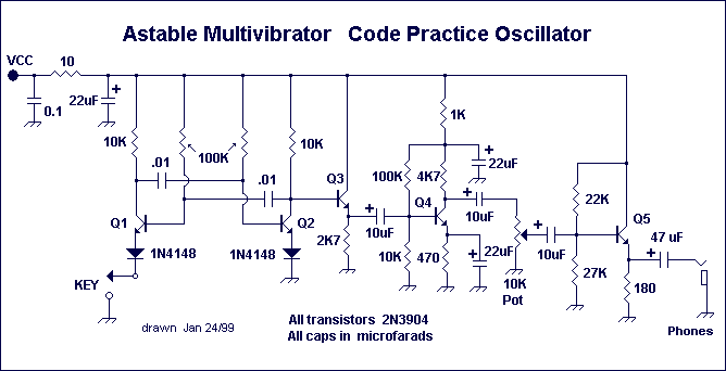
Astable or free-running multivibrators have been used in home-built amateur radio equipment for many years. The basic circuit is a two-stage amplifier with AC-coupled feedback from output to input. One transistor stage is on (conducting current) while the other...
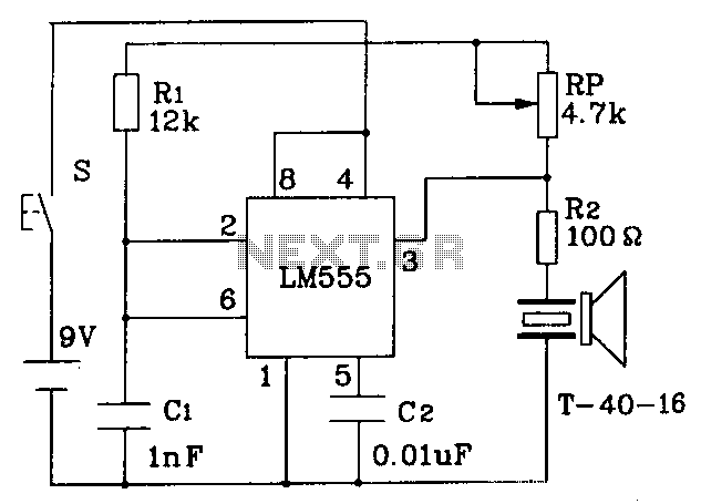
The circuit operates at a distance of 3 feet from the oscillating pulse output of a 555 timer generating a 40kHz signal, driving a T-40-16 transducer to emit ultrasonic signals at the same frequency. The circuit is powered by...