
astable Multivibrator

The NE555 timer IC is a versatile device commonly used in various timing, pulse generation, and oscillator applications. When configured in astable mode, the NE555 operates as a free-running multivibrator that continuously switches between its high and low states, producing a square wave output. This configuration is often employed for generating clock pulses, LED blinkers, or tone generation.
To build an astable multivibrator using the NE555, the following components are typically required:
1. **NE555 Timer IC**: The core component of the circuit.
2. **Resistors (R1 and R2)**: Two resistors are needed to set the charge and discharge times of the timing capacitor. The values of these resistors will determine the frequency of the output signal.
3. **Capacitor (C1)**: A timing capacitor that works in conjunction with the resistors to establish the oscillation frequency. The capacitance value directly affects the timing intervals.
4. **Power Supply**: A DC power source, typically between 4.5V to 15V, is required to power the NE555.
5. **Output Load**: This could be an LED, speaker, or any other load that will be driven by the output signal.
The configuration of the circuit involves connecting the resistors and capacitor in a specific manner. The discharge pin (pin 7) is connected to the junction of the two resistors, while the timing capacitor is connected between this junction and ground. The threshold (pin 6) and trigger (pin 2) pins are connected together, allowing the circuit to reset and trigger itself continuously. The output (pin 3) provides the square wave signal.
When designing the circuit, it is crucial to calculate the frequency (f) of oscillation using the formula:
\[ f = \frac{1.44}{(R1 + 2R2) \cdot C1} \]
Where:
- \( R1 \) is the resistance connected to the supply voltage,
- \( R2 \) is the resistance connected to the discharge pin,
- \( C1 \) is the timing capacitor.
Additionally, the duty cycle can be adjusted by varying the resistor values, allowing for customization of the output signal characteristics.
In summary, the NE555 astable multivibrator circuit is an efficient and straightforward solution for generating periodic signals, with a wide range of applications in electronics. Proper understanding of the component values and configuration is essential for successful implementation.With an NE555 you are also able to build an astable multivibrator or blinker. Find out how, and what you need to be aware of.. 🔗 External reference
Related Circuits
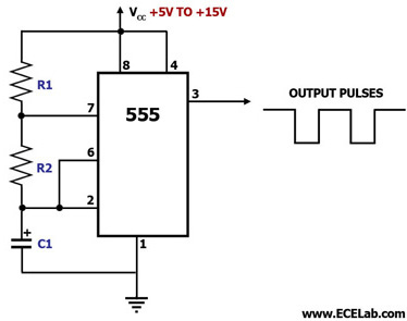
This circuit diagram illustrates the configuration of a 555 timer integrated circuit (IC) as an astable multivibrator. An astable multivibrator is a timing circuit characterized by unstable 'low' and 'high' states. Consequently, the output of an astable multivibrator continuously...
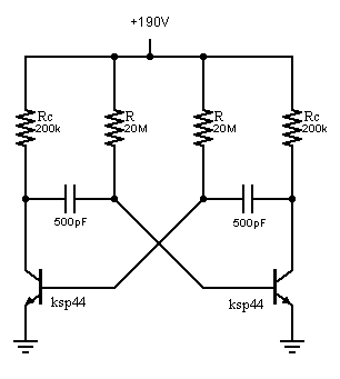
An oscillator is being developed to operate within the 200V range, targeting a frequency of approximately 1 kHz while minimizing current consumption. Initial testing has commenced. The design of a high-voltage oscillator capable of operating at 200V and generating a...
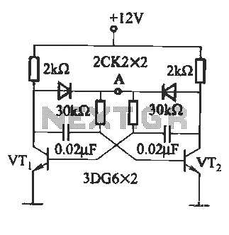
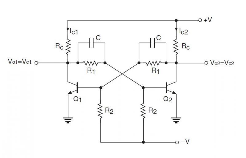
The circuit illustrated in Figure (A) consists of resistors R1 and R2 with values ranging from 15 to 18 kΩ, and capacitors C1 and C2 with capacitance values between 0.01 µF and 10 µF. Figure (B) depicts the oscillation...
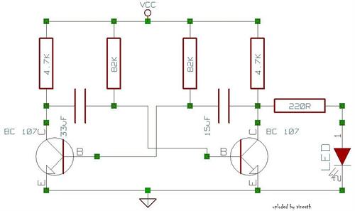
An astable multivibrator is a switching circuit that alternates its output on and off for a designated time period. This device, also known as a free-running oscillator circuit, is primarily utilized to generate square waves over a specified duration....
An astable multivibrator needs to be designed, and the maximum and minimum frequencies generated at the output must be calculated. An astable multivibrator is a type of oscillator circuit that continuously switches between its high and low states without requiring...
Multivibrators, unlike sinusoidal oscillators, are circuits with regenerative feedback that produce pulsed outputs. There are three primary types of multivibrators: the Bistable Multivibrator, the Monostable Multivibrator, and the Astable Multivibrator. A bistable multivibrator circuit maintains stable LOW and HIGH...