
Continuity in Circuit Tester
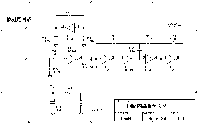
The continuity tester circuit is designed to assess the integrity of electrical connections within a circuit board. It operates effectively at lower voltages, ensuring that semiconductors, which typically do not conduct at these levels, can be evaluated without causing damage. The primary function of this tester is to identify short circuits and verify that unaffected components remain operational.
The schematic for the continuity tester incorporates both digital integrated circuits (ICs) and analog components. The input threshold is set at 1/2Vcc, which allows the circuit to function optimally within its designed voltage range. The output voltage is maintained at approximately 1.7V, which is crucial for providing feedback to the inverter stage of the circuit. This feedback mechanism ensures that the inverter operates correctly, allowing for accurate continuity testing.
The circuit is capable of measuring voltage drops as low as 0.2V. When the voltage at the input exceeds 1.5V, the circuit activates an oscillator that drives a buzzer, providing an audible indication of continuity. The semiconductor components in the circuit typically exhibit a voltage drop ranging from 0.5V to 0.6V during conduction, which is a critical parameter for assessing the performance of the circuit.
Furthermore, the continuity tester is designed to detect pure resistance below 500 ohms, indicating that connections are solid and without significant resistance that could lead to circuit failure. This feature is essential for ensuring that all components within the circuit board are functioning correctly and that there are no interruptions in the electrical pathways.Continuity tester to check continuity in the circuit (Insakittochekka) is. The continuity check over the circuit board wiring that can be checked at a lower voltage semiconductors do not conduct contained in the circuit, you can just check the wiring short miscarriage pure unaffected parts. Schematic that I'll know to take a look and are used in digital IC and analog operation. First, using Input Threshold 1/2Vcc to become, over the output voltage to approximately 1.7V feedback to keep the inverter, and output it. Circuit to measure voltage drop of 0.2V or less, the voltage of 1.5V and above the recipient, the buzzer will sound running oscillator.
The conduction of the semiconductor ring because the voltage drop to around 0.5 ~ 0.6V. If the sound is pure resistance below 500?. 🔗 External reference
Related Circuits
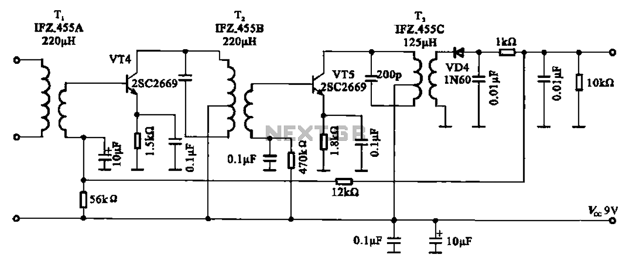
AM radio shows the IF amplifier and detector circuit. The mixer receives the intermediate frequency output signal from the transformer after the device. This signal is applied to the base of the intermediate frequency transistor VT4. The collector load...
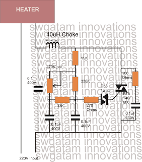
Controlling heaters rated up to 1500 watts requires stringent specifications for the controlling unit to ensure safe and effective operation. The introduction of advanced snubber-less Triacs and Diacs has made it relatively easier to implement heater controllers at high...
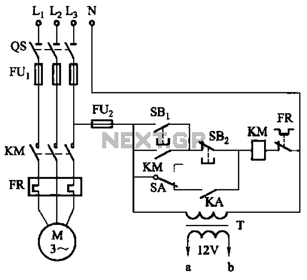
The circuit illustrated in Figure 3-81 employs a transistor delay circuit to facilitate start-stop cycle control. It can operate in both manual and automatic modes. The circuit is primarily governed by the motor run time circuit, which includes transistors...
After conducting experiments with a rotary encoder connected directly to keyboard switches, it was found that the keyboard controller IC (an Intel P8049AH in this case) is unable to detect pulses that are too narrow. Testing involved rotating the...
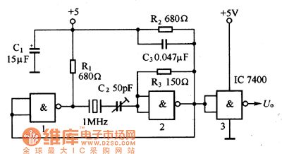
The oscillator circuit consists of a 1MHz quartz crystal resonator and a NAND gate, with the output buffer stage provided by NAND gate 3. This circuit can be utilized for calibrating standard frequency. The described oscillator circuit operates at a...
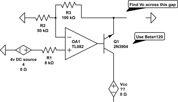
The voltage measured at 12V after the emitter is perplexing, especially when the output from the op-amp is +15V, suggesting a 3V drop across the transistor. This raises questions about the expected gain of 2, which would imply an...