
not so tiny power meter
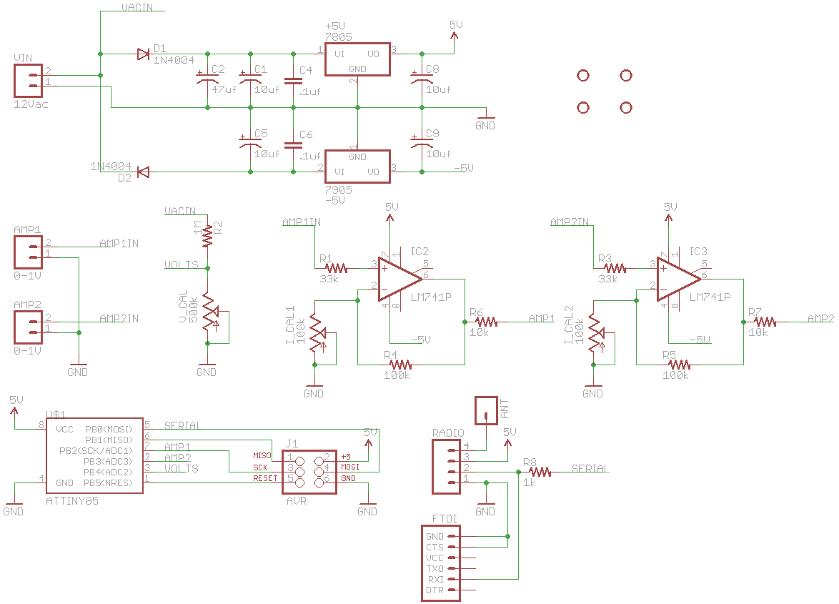
The Not So Tiny Power Meter is a comprehensive solution for monitoring electrical consumption across multiple appliances within a residential setting. It is designed to provide detailed measurements of electrical parameters, including voltage, current, power factor, and frequency, using a straightforward and cost-effective approach.
The core of the device is based on the ATtiny85 microcontroller, which is well-suited for handling the analog-to-digital conversion (ADC) necessary for capturing voltage and current measurements. The device employs volt-meter current clamps to measure the current flowing through various circuits, while an AC transformer powers the entire system. The transformer steps down the AC voltage to a manageable level, which is then reduced further using a voltage divider to ensure it falls within the ADC's input range.
The design incorporates a dual-sided half-wave rectifier that generates both +5V and -5V power rails, allowing for stable operation of the microcontroller and associated circuitry. Two operational amplifiers (op-amps) are utilized to scale the output from the current clamps before it is fed into the ADC. This scaling is crucial for ensuring that the sampled values are within the ADC's range, thus improving measurement accuracy.
To enhance the functionality of the device, the ATtiny85 samples the voltage and current waveforms over a complete cycle of the 60Hz AC signal. By capturing the peak values of these waveforms, the device can calculate the RMS values necessary for determining power consumption and power factor. The use of a timer, extended to 16 bits in software, allows for precise measurement of the time intervals between peaks in the voltage and current waveforms, facilitating accurate frequency and power factor calculations.
The design also incorporates protective measures to ensure the integrity of the ADC inputs. Protection diodes and input resistors prevent damage from negative voltages that may occur during sampling. This thoughtful design consideration ensures the longevity and reliability of the device.
Overall, the Not So Tiny Power Meter represents an innovative and practical approach to energy monitoring, providing valuable insights into power usage while remaining user-friendly and cost-effective. The integration of various measurement techniques within a single microcontroller platform exemplifies the potential for DIY solutions in the field of electrical engineering.The Kill A Watt is an awesome product; it measures volts, amps and power factor of an individual appliance which can be used to calculate power, cost to run, etc. It`s also quite hackable. But I wanted something that would give me the same data for my whole apartment. After some Googling, the best I could find was this project from picobay, but I didn`t want to invest in an expensive network IO platform. There were also some off-the-shelf solutions, but they too were expensive and limited. Well, time to design my own solution then. Enter what I call the Not So Tiny Power Meter`. The catchy name comes from the microcontroller I used, ATtiny85, and some sizing issues I had with the enclosure. I started out with a plan to use volt-meter current clamps just like the project I linked above (photo of clamp from picobay.
com) and use a dedicated chip, the AD736, to convert the AC signal off the clamps to a DC voltage representing the RMS current value. The chips are expensive, tough to use as I found out, and still require external amplifiers to scale up the value to 5V ADC range.
So I nixed that idea. Instead, I decided to use a single op-amp to scale up the AC voltage off the clamp and sample it directly with the ATtiny`s ADC. The circuit would be cheap and easy to design and I can convert the signal to RMS in code. Then I had a thought. If I`m sampling directly, why not measure more than just amps As an EE, I`d love to know more about my power usage, like power factor, frequency, and a more accurate measure of power by not assuming a voltage like most other projects; but I still wanted to keep the device simple.
Then I had another thought: Why not measure voltage through the same transformer that`s giving my circuit power After a few tests, I found that a properly designed rectifier and regulation circuit wouldn`t distort the source AC waveform too much. They key was to keep the values of the capacitors before the voltage regulator (circled in red) to a minimum, just enough to support a stable DC voltage.
Anymore and the inrush when the rectifier diode starts conducting severely distorts the AC wave form. My design is simple. An AC transformer powers the circuit and a voltage divider drops the source voltage down to ADC range for measuring.
A dual sided half-wave rectifier and regulation circuit provides +5V and -5V rails. The AC signals off two AC clamps are scaled up using two op-amps. I planned on using trim potentiometers to calibrate the gains of all the measurement circuitry, but found it was easier to just use transfer functions (found with experimentation) in code. Everything is measured with an ATtiny85, and transmitted out of the breaker panel by a cheap RF transmitter.
Since all sources are AC, the ATtiny could only read the positive half of the waveforms. When the signal would go below the ATtiny`s GND, the protection diodes and input resistors would protect the ADC pins from damage. With this design, I can measure voltage & frequency off one phase and current & power factor off both phases.
The theory of operation is simple. First, the ATtiny85 will repeatedly sample the volts ADC pin for over a full period of the 60Hz sine wave. The peak value of the samples is remembered. Repeat for both current clamp ADC pins. After the max values are captured, the ADC clock is increased for faster sampling, with higher errors.
To measure frequency and power factor, I used a 8 bit timer that I extended to 16 bit in software. Using the timer, I measure the difference in time between two peak values of the voltage waveform. Then, I measure the difference in time between a peak value of the volts waveform, and a peak value of the current clamp waveform. Repeat for the second clamp. After all these measurements, some conversions are done to convert the peak values to RMS, times to frequency and power factor, run through a transfer function to account for various gains in t
🔗 External reference
Related Circuits
The most challenging aspect of the build was to find or design a circuit capable of handling the load while remaining within budget. This circuit achieves both objectives. It adjusts the power output using a potentiometer (variable resistor) R1,...
When signing into developerWorks for the first time, a profile is automatically created. Certain information from this profile, such as name, country or region, and company, is made public and will be associated with any content posted. Users have...
This document outlines a revised version of an LM35-based digital thermometer project previously shared. While it is a straightforward project, it remains popular among beginners learning about microcontrollers. The initial version contained a flaw, as some readers noted that...
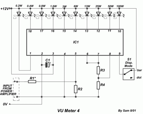
The circuit is connected in parallel with the output of the power amplifier and provides the signal level from the output. By adjusting resistance R1 in the input circuit, the power indication can be adapted according to the resistance...
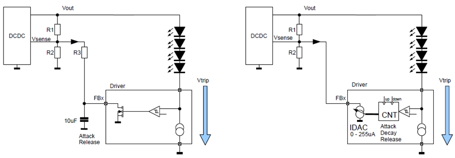
New design techniques in LED driver circuits promise to deliver significant energy savings that will help TV manufacturers meet stringent power consumption requirements. The advancement of LED driver circuits through innovative design techniques has the potential to yield substantial energy...
Circuit diagram for a DC power supply protection circuit. The device includes a buck rectifier power supply, a monostable delay circuit, a relay control circuit, and an audio feedback oscillation circuit. The entire circuit operates with a DC voltage...
Warning: include(partials/cookie-banner.php): Failed to open stream: Permission denied in /var/www/html/nextgr/view-circuit.php on line 713
Warning: include(): Failed opening 'partials/cookie-banner.php' for inclusion (include_path='.:/usr/share/php') in /var/www/html/nextgr/view-circuit.php on line 713