
NSH Field Strength Meter
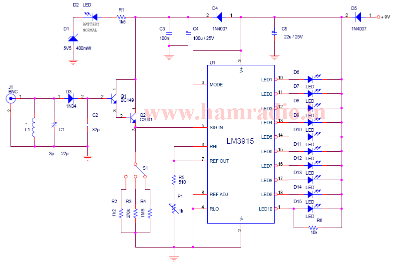
The design and implementation of this field strength meter (FSM) offer a practical solution for evaluating antenna performance in various settings. The FSM's ability to measure effective radiation and visualize field strength through a multi-colored LED display enhances usability, especially in low-light conditions. The logarithmic display provided by the LM3915 ensures that users can quickly assess signal levels, facilitating comparisons between different antenna types and configurations.
The choice of components, such as the air-cored inductor and high-gain transistors, contributes to the sensitivity and accuracy of the FSM. The adjustable sensitivity through the resistor selection allows for tailored measurements based on specific requirements, making this FSM versatile for different applications. Furthermore, the metal enclosure not only protects the internal circuitry but also minimizes interference, ensuring reliable readings.
In educational contexts, this FSM serves as a valuable tool for understanding RF radiation principles, antenna characteristics, and the effects of various configurations on radiation patterns. By enabling hands-on experimentation, users can gain insights into the complexities of RF systems and improve their practical skills in electronics and telecommunications. Overall, the FSM represents a cost-effective and efficient solution for antenna testing and analysis, suitable for both hobbyists and professionals in the field.A well tuned antenna system works like a dummy load, i. e. the SWR is 1. 2:1 or below but the hunting range is low. What`s wrong Insufficient radiation How to know that Yes, this is what the article about. You can measure the effective radiation using a field strength meter (FSM). A commercial FSM can measure the loss or gain of radiation, testin g polarisation, plot the radiation pattern for the various antennas for comparison. The cost for a commercial FSM can vary from Rs 1500/- to Rs 5000. But this design one can assemble for a few hundred. The Standard Analog Meters or LCD - DVM based FSM are some what DEAF and the meter level movement can`t be read from a distance of around 5 ft and above. To avoid this problem, this FSM is having a 10 level multi coloured 3mm LEDs for level reading; this will give a fair reading up to 20 ft + distance even at night.
The FSM will give RF radiation reading; picked through the air, that shows an antenna`s gain of radiation. Due to this REAL READING, one can compare different types of antennas gain, angle of radiation, polarization etc.
The FSM sniffs out bad coax, connectors or improperly grounded transmitter. It is a good instrument to plot radiation patterns of yagis / verticals. It is an educational tool for studies. SWR meter cannot do or detect some measurements about RF. But this FSM will do!. When Working with different types of input RF signal levels, the sensitivity of the NSH FSM can be controlled by changing different types of sensing antennas. Remember that, VSWR meter only shows that the antenna is fully loading and shows a low reflected power or very low SWR, but it does not mean that the antenna is efficiently radiating the TX power into AIR - The only tool that shows the exact on-air radiation levels is FSM.
This FSM is designed to work on 2 meter (144 - 146 MHz). A tuned L-C circuit at input is used to make the FSM selective for the desired band. The heart of this circuit is LM3915 dot/bar display driver from National Semiconductors, providing a logarithmic 3dB/step analog display. Disconnecting 1C1 pin 9 from +ve supply, changes the display from a bar graph to a moving dot display, hence reducing the total power consumption.
In bar graph mode, up to 100mA may be drawn from the battery when all LEDs are on. The FSM can be powered by a 9V(6F22) battery. The inductor L1 consists of 2. 5 turns of 22 SWG enamelled copper wire, and the internal diameter is 7mm and air core. The two transistors forms a high gain amplifiers and the output voltage is depends on the resistor selected (L, M, H) by the sensitivity selector S1. The circuit should be installed in a metal box. Three LEDs of green, three LEDs of yellow, three LEDs of orange and finally two LEDs of red are arranged in increasing order for the field strength levels.
The highest level of LED is wired to pin 10 and lowest level LED is wired to pin 1 of IC1. For tuning this FSM, connect the rubber flux antenna to the input of the FSM, and kept vertical. Select 145 MHz in the hand held, select 500 mW and, set up and try FSM at reasonable distance. Key the transceiver and read the segment. If it is full increase the distance between, till one or two LED to glow. Then trim C1 for getting more LED to lit. LED brightness can be adjusted by P1 if necessary. 🔗 External reference
Related Circuits
A densitometer is an essential tool for darkroom enthusiasts. Traditionally, densitometers were costly and bulky, and those capable of interfacing with computers to calculate effective film speed, contrast index, or gamma were largely inaccessible to amateur photographers. However, advancements...
This design is for a thermometer circuit that utilizes the LM35 integrated circuit (IC) as a temperature sensor. It is a straightforward circuit that allows for the measurement of room temperature using a digital voltmeter or any voltmeter capable...
This circuit is designed to measure the voltage of a 12V nominal lead-acid rechargeable battery system. While it was specifically created for solar-powered systems, it is versatile enough for use in automotive or other 12V applications. Lead-acid batteries typically...
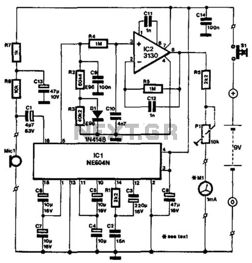
The NE604's signal-strength indicator section utilizes an internal logarithmic converter, allowing for a linear decibel scale. This feature enables the replacement of the moving-coil meter depicted in the diagram with a digital instrument. The assumed signal source is an...
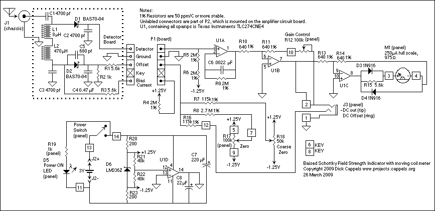
When an antenna is attached, or even if not, in the presence of a strong RF field, the field strength meter has a moving coil meter to indicate relative field strength. The box holds a Schottky diode detector, a...
AC level meters, such as VU meters, and DC level meters, such as signal meters, are used for measuring electrical signal levels. These devices feature a display consisting of nine red or green LEDs that represent the input level...