
meter circuit
AC and DC level meters serve essential roles in audio and signal processing applications by providing visual feedback on signal strength. The VU (Volume Unit) meter is particularly significant in audio engineering, as it helps in monitoring audio levels to prevent distortion and ensure optimal sound quality. The DC signal meter, on the other hand, is utilized in various electronic applications to gauge the strength of direct current signals.
The display of these meters is constructed using nine LEDs, which illuminate in red or green, depending on the input signal's level. This bar graph representation allows for quick visual assessment of the signal strength, with each LED corresponding to a specific range of input levels. The use of color coding enhances usability, as users can instantly identify whether the signal is within an acceptable range (green) or approaching critical levels (red).
The input amplifier is a crucial component of these meters, designed to accommodate a broad spectrum of input signals. It amplifies the incoming signal to a level suitable for accurate measurement and display. This wide bandwidth capability ensures that the meter can be used in various applications, from low-level audio signals to higher voltage levels in industrial settings.
In summary, AC and DC level meters are vital tools in both professional audio environments and general electronics. Their LED displays provide clear visual feedback, while the input amplifiers ensure versatility across different signal types and levels, making them indispensable for effective signal monitoring and management.AC level meters such as VU meters. . DC level meters such as signal meters. Functions. Display Nine red or green LEDs display the input level in the shape of a bar. . Input amplifier Wide. 🔗 External reference
Related Circuits
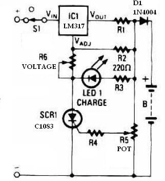
This schematic circuit for a battery charger consists of very few components but operates effectively. When power is applied to the circuit, SCR1 remains off, preventing any bias current from flowing to ground. The LM317 voltage regulator is connected...
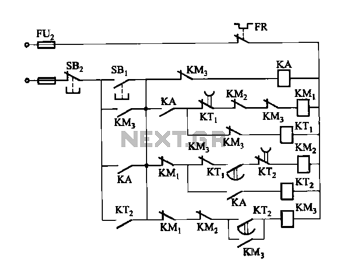
Figure 3-118 illustrates an automatic acceleration control circuit. This circuit employs a male contactor time relay, enabling the motor to start automatically at a low speed before transitioning to high-speed operation. The automatic acceleration control circuit depicted in Figure 3-118...
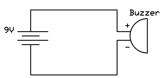
This project involves connecting the positive terminal of the battery to the positive lead of the buzzer and the negative terminal of the battery to the negative lead of the buzzer. Typically, the positive lead of the buzzer is...
Audio levels can be monitored using a small panel meter with this circuit built from discrete components. The circuit has a flat frequency response from about 20Hz to well over 50Khz. Input sensitivity is 100mV for a full scale...
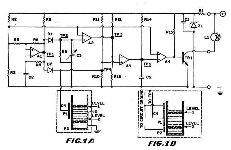
Figure 1 (A) depicts the circuit diagram of one embodiment of the fluid level detector designed. The circuit is typically powered by a 12-volt automobile battery, which is reduced to a 5-volt DC source using a voltage regulator consisting...
One of the critical components is a PWM speed controller, allowing for fine speed adjustments instead of just an "on" mode that runs at full power. This is important for safety. A basic stamp microcontroller was purchased, which includes...