
NTC phase asynchronous motor protection circuit
The semiconductor thermistor serves as a critical component in thermal protection systems, particularly in electrical applications where monitoring and managing temperature is essential for operational safety and efficiency. The thermistor's sensitivity to temperature changes allows it to provide real-time feedback on the thermal state of the winding, which is crucial in preventing overheating and potential damage to the motor or other electrical components.
In a typical configuration, the thermistor is strategically placed near the three-phase stator windings to ensure accurate temperature readings. The use of epoxy cement not only secures the thermistor in place but also provides additional insulation and protection against environmental factors. The choice between NTC and PTC thermistors depends on the specific application requirements; NTC thermistors are generally used for applications requiring a decrease in resistance with increasing temperature, while PTC thermistors are used where an increase in resistance is desirable as temperatures rise.
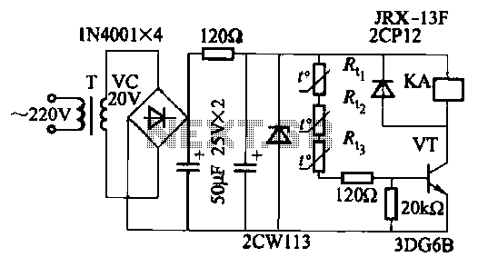
The circuit design, as indicated in Figure 4-1, incorporates a switch circuit based on a single tube amplifier, which is essential for amplifying the signal from the thermistor. This amplification is necessary for effective temperature monitoring and control, ensuring that the system can react promptly to any changes in temperature. The selection of the appropriate thermistor type, such as RRC6 or MF-15, is critical, as it affects the accuracy and responsiveness of the temperature measurements. The specified resistance values at different temperatures provide insight into the thermistor's behavior and its suitability for the intended application.
Overall, the integration of a semiconductor thermistor in a thermal protection circuit enhances the reliability and safety of electrical systems, making it a vital component in modern electronic designs.Semiconductor thermistor embedded thermal protection element belongs, it is sensitive to temperature, temperature error of 5. Its reliability, small size (diameter 3. Smm), easy to install, easy to embed winding, use it as a temperature sensing element can effectively reflect the electrical winding temperatures motivation. Thermistor on the three-phase stator windings, close to the wire, with epoxy cement. Thermal resistance has a negative temperature coefficient thermistor (NTC) and positive temperature coefficient thermistor (PTC) of the points. Circuit shown in Figure 4-1. Wherein Figure 4-1 (b), (c) only one shown protection circuits, the main circuit not shown. They are a switch circuit consisting of a single tube amplifier. Thermistor brother., R. ., R., The choice RRC6 type or MF-15 type (lokfl, 20 ), this thermistor in about lkfl 100 when, 110 at about 0.6k, Cl.
Related Circuits
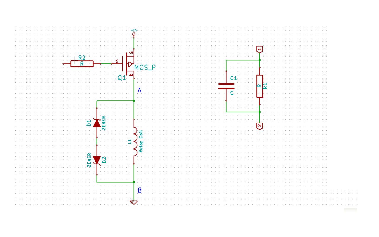
Although this may be a basic question, there is still some struggle with it. In this schematic, two zener diodes D1 and D2 are connected back-to-back across relay coil L1. The breakdown voltage (BVds) is -30V for Q1. The...
When a new computer modem is introduced into a home, the demand on the phone line increases significantly. Internet users can consume phone time similarly to a chatty teenager. Additionally, computer modem users often prioritize their privacy; for instance,...
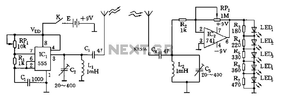
The circuit diagram of the device features a 555 timer IC configured as a transmitter and a receiver, divided into two sections. The 555 timer in the transmitter section serves as the core component of a frequency oscillator. The...
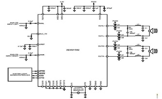
This is a typical stereo application circuit schematic of the ADAU1592, a 2-channel, bridge-tied load (BTL) switching audio power amplifier. The ADAU1592 can be utilized in flat panel televisions, PC audio systems, and mini-component applications. The ADAU1592 is designed to...
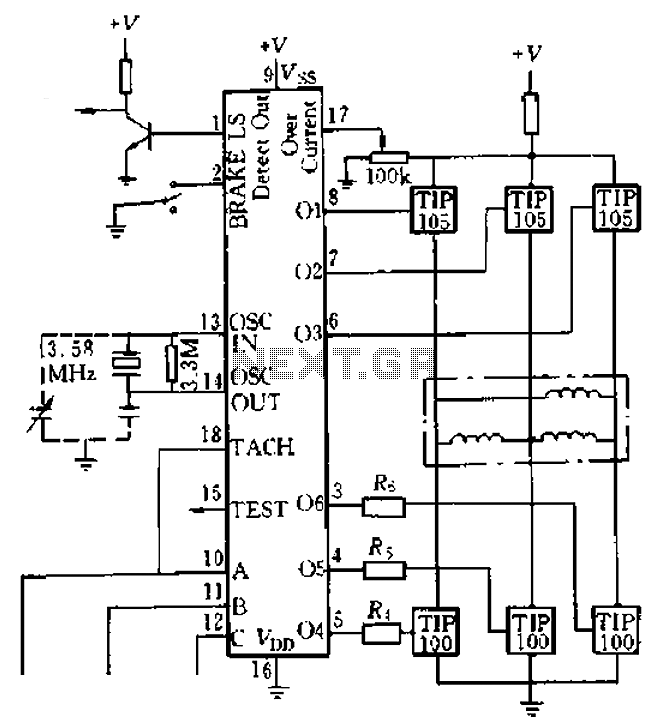
Four application examples are presented in the figure, focusing on a three-phase brushless DC motor used in Winchester disk drives with an operating speed of 3600 RPM. Although the original design specifies an operating speed of 3600 RPM, alternative...
The artwork style of the operational amplifier and the meter face suggests that it is an ACC design from an old issue of ACC Notes. The second image was scanned, and the text below was written from scratch. If...
Warning: include(partials/cookie-banner.php): Failed to open stream: Permission denied in /var/www/html/nextgr/view-circuit.php on line 713
Warning: include(): Failed opening 'partials/cookie-banner.php' for inclusion (include_path='.:/usr/share/php') in /var/www/html/nextgr/view-circuit.php on line 713