
LS7263 Application Circuit Example

The described system revolves around a three-phase brushless DC motor, which is integral to the operation of Winchester disk drives. This type of motor is favored for its efficiency and reliability in high-speed applications. The standard operating speed of 3600 RPM can be adjusted based on specific requirements, demonstrating the adaptability of the motor design.
The LS7263-02 circuit plays a pivotal role in speed control. It utilizes a 2.68 MHz crystal oscillator that provides a stable frequency reference for the motor control system. By integrating a tachometer signal, the circuit can accurately measure the motor's rotational speed and enable precise speed adjustments. This feedback mechanism is essential for maintaining the desired performance and ensuring the motor operates within specified parameters.
For applications requiring higher speeds, the configuration allows for an increase to 5400 RPM, showcasing the versatility of the motor control system. Conversely, when a variable frequency oscillator is implemented, the system can be tuned to lower speeds, such as 1500 RPM or even less. This flexibility makes the motor suitable for a wide range of applications, from high-speed data retrieval in disk drives to low-speed operations in other electronic devices.
In summary, the three-phase brushless DC motor employed in Winchester disk drives is characterized by its adjustable speed capabilities, facilitated by the LS7263-02 circuit and crystal oscillator. The potential for both high and low-speed operations enhances its applicability in various electronic systems.4 Application examples of applications are given in the figure, it is a Winchester disk drives three-phase brushless DC motor, the operating speed is 3600r/min. Although the or iginal design of the circuit operating speed is 3600r/min, but other speed may also be used. For example, the use of LS7263-02 circuit, with the government 2.68MHz crystal oscillator oscillator, plus a tachometer signal to divide the circuit, you can get an accurate 5400R/mn. If the crystal oscillator circuit with a variable frequency oscillator instead of t LS7263 also allows the motor to work in 1500r/min or less speed.
Related Circuits
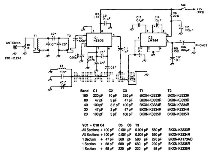
Note that T1 and T2 are TOKO components, including part numbers for the coils T1 and T2. The direct-conversion receiver shown utilizes a double-tuned input network made from readily available TOKO coils. IC1, an NE602, serves as a voltage-controlled...
LEDs lining the headliner will fade in when the door is opened and fade out when the door is closed. The necessary components include a circuit to utilize 12V power from the vehicle to illuminate 15 LEDs and control...
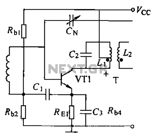
A common intermediate frequency amplifier circuit is presented, along with its components and parameters. The reference values for the components are as follows: 1) Transistors: VT1 to 3DG19, Vcc = 6V. 2) Resistance values: R1 = 50 kΩ, R2...
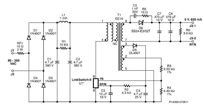
A simple 3.25W constant voltage/constant current (CV/CC) charger can be designed using the LinKSwitch family IC manufactured by Power Integrations. This electronic circuit project is intended to provide a 5-volt output with a maximum current of 650mA. The 3.25W...
The main ΣΔ loop operates in steady state and is fully controlled by summing comparator Q2. This comparator amplifies the ripples of the sensed inductor current and output voltage with gains KI and KV, respectively, to generate an internal...
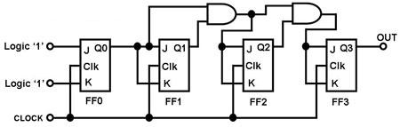
The circuit in Figure 1 is a 4-bit asynchronous counter, also known as a ripple counter. It consists of four J-K flip-flops with their J and K inputs connected to logic 1. This configuration causes the output of each...