
The Simplest Car Battery Charger
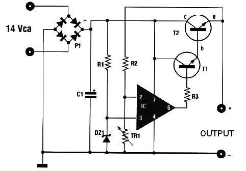
The circuit described functions as a straightforward battery charger utilizing a transformer, two diodes, a smoothing capacitor, and an ammeter to monitor the charging current. The transformer steps down the AC voltage from the mains supply to a lower voltage suitable for battery charging. The two diodes are configured in a full-wave rectifier arrangement, allowing both halves of the AC waveform to be utilized, which improves the efficiency of the charging process.
When the circuit is powered, the AC voltage from the transformer is rectified by the diodes, converting it into pulsating DC voltage. The smoothing capacitor is crucial in this configuration as it reduces the ripple in the output voltage, providing a more stable DC voltage to the battery. This is particularly important when the circuit is used as a battery eliminator, where a steady voltage is required for devices that operate on 12V DC.
The ammeter is an essential component for monitoring the charging current flowing into the battery. A reading of 1-3 amps indicates that the battery is in the charging phase. As the battery approaches full charge, the current diminishes, and the ammeter will eventually read zero or nearly zero. This behavior is a signal to disconnect the battery to prevent overcharging, which can damage the battery.
It is imperative to connect the + and - terminals correctly to avoid damage to the circuit and the battery. Reversing the polarity can lead to circuit failure or battery damage. Overall, this circuit efficiently charges a battery while providing essential feedback through the ammeter, ensuring safe and effective operation.This very simple circuit uses a transformer ,two diodes , a capacitor and an ammeter. To charge a battery just connect the + and - terminals of the circuit to the corresponding terminals of the battery. When the battery is not charged, the ammeter reading shows 1-3 amps. When the battery is fully charged the ammeter reads Zero or nearly zero, after which the battery should be removed from the charger.
The circuit is a full wave rectifier using 2 diodes for rectification. The capacitor is used for smoothing. I think the circuit works fine without the capacitor since the battery itself acts a BIG capacitor. But when you are using the circuit to supply 12V (as a battery eliminator) the capacitor needs to be present. Care should be taken NOT to reverse the + and - terminals while connecting it to the battery. 🔗 External reference
Related Circuits
This automatic battery charger circuit is ideal for charging batteries used in alarm systems that require battery buffering. Caution must be exercised when connecting the battery to ensure correct AC polarity. It is essential to meticulously follow the schematic...
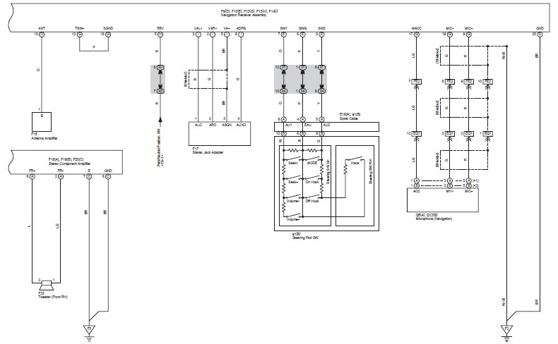
This document contains the wiring diagram for the 2007 Toyota Camry, specifically for the GSV40 and ACV40 series. It details the electrical circuits present in the vehicles, categorizing them by system for clarity. The wiring for each system is...
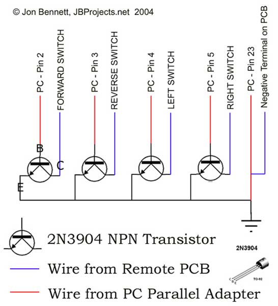
This project article was originally written in 2004 when most computers had parallel ports. This is no longer the case, so much of this information is now outdated. The Mini RC Car Project has been one of the most...
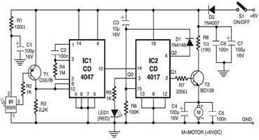
The following circuit illustrates an infrared toy car motor controller. This circuit is based on the 4047 and 4017 integrated circuits (ICs). Features: 16V. The infrared toy car motor controller circuit utilizes two primary integrated circuits, the 4047 and the...
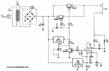
This battery charger circuit is regulated and adjustable, enabling it to charge most NiCAD batteries. It can accommodate both single cells and multiple battery cells connected in series or parallel. The maximum voltage of the batteries should not exceed...
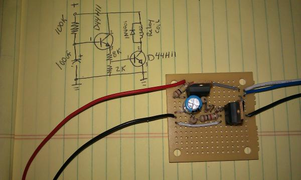
The momentary hold relay board and the accessory delay module are components designed for automotive applications. The momentary hold relay board powers the GPS unit and the tablet, eliminating the need for manual button activation. The accessory delay module...
Warning: include(partials/cookie-banner.php): Failed to open stream: Permission denied in /var/www/html/nextgr/view-circuit.php on line 713
Warning: include(): Failed opening 'partials/cookie-banner.php' for inclusion (include_path='.:/usr/share/php') in /var/www/html/nextgr/view-circuit.php on line 713