
Obstacle Avoiding Robot without microcontroller

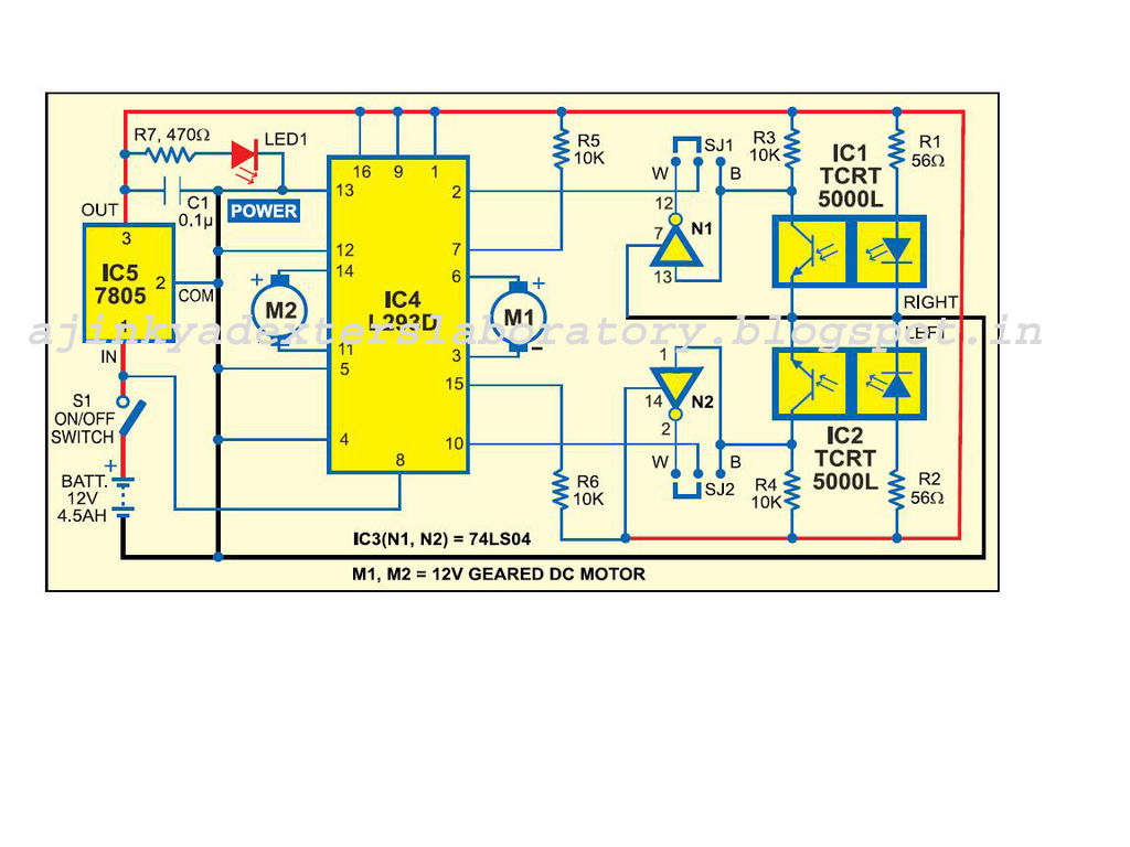
The obstacle-avoiding robot operates using a combination of sensors and simple electronic components. The primary components include infrared (IR) sensors, a motor driver IC, and a power supply. The IR sensors are positioned at the front of the robot to detect obstacles by emitting infrared light and measuring the reflection. When an object is detected, the corresponding sensor sends a signal to the motor driver IC, which controls the direction of the motors connected to the wheels.
The circuit is powered by a 9V battery, which is regulated down to 5V using an IC 7805 voltage regulator to supply the necessary voltage for the sensors and the motor driver. The motor driver IC allows for bidirectional control of the motors, enabling the robot to turn left or right based on sensor input. The assembly of components on a breadboard facilitates easy modifications and troubleshooting.
The robot's functionality can be tested in various environments, including indoor and outdoor settings, to assess its ability to navigate around different types of obstacles. Adjustments to the sensitivity of the IR sensors can be made to improve performance in diverse conditions. The design encourages experimentation, allowing users to explore additional features such as speed control or the addition of more sensors for enhanced obstacle detection.
In summary, the obstacle-avoiding robot serves as an excellent introduction to robotics, combining basic electronic principles with practical application. The project is accessible to beginners and provides a foundation for further exploration in the field of robotics.An obstacle avoiding robot is an intelligent device, which can automatically sense and overcome obstacles on its path. It is developed without micro-controller in order to eliminate critical circuits, difficult programming etc.
All you want to do is to just understand the circuit diagram and start doing this robot. This simple technique can be inc orporated in wheeled robots to keep them away from damages and accidents. This intelligent robot requires several components to bring them alive. Itdoesn`tcost too much, and easily available in all electronics markets as well. Thecircuit diagramof obstacle avoiding robot is shown in the above picture. It could utmost help you to develop this robot with ease. In case, if you are new to robotics, observe the followingstep by step instructionsof all connections given below. Take the positive supply from battery holder via breadboard wire and place it in IN of IC 7805, and also connect its negative supply in last row of breadboard.
After finishing the assembling work, connect the 9V battery via battery snap. Then, see what happens. The robot will automatically start traveling on the unstructured path without hitting any objects. When the left IR module senses any obstacles on its way, it will turn right till it stops sensing. Similarly, it will turn left when the right IR module senses obstacles. If both the sensors sense an obstacle, then the robot will stop moving. The concept of developing an Obstacle Avoiding Robot may be simple, but you may meet some obstacles in implementing it. Overall, I feel the above details are well-enough to complete this intelligent robot. It will cost approximately $40 U S Dollars to develop one. You can try it in your free time, and any quires related to it are most welcomed. 🔗 External reference
Related Circuits
The Atmel AVR series are very good microcontrollers with quite a rich instruction set, rich enough that lots of folks have good compilers for them so we don’t have to learn their assembler. A very rich compiler available is...
Cellphone Operated Land Rover (Mobile Phone Operated Robot). In this project, the robot is controlled by a mobile phone that makes a call to the mobile phone attached to the robot. The cellphone operated Land Rover project involves the design...

The FX919A is a CMOS integrated circuit that includes all necessary baseband signal processing and Medium Access Control (MAC) protocol functions for a high-performance 4-level Frequency Shift Keying (FSK) Wireless Packet Data Modem. It interfaces with the modem host...
Carefully examine the following circuit diagram and attempt to construct the circuit on a breadboard first. If it functions correctly, proceed to create its PCB version. The circuit diagram serves as a blueprint for constructing an electronic circuit on a...
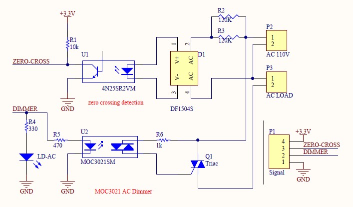
Have you verified whether you can see the zero crossings on your input pin? It may be beneficial to write a sketch that toggles the LED on pin 13 every 50 or 60 zero crossings. This should result in...
This low-cost bass treble circuit consists of capacitors, resistors, and two potentiometers for bass and treble control. The circuit can be assembled without a veroboard, as the components can be soldered directly due to the simplicity of the design....