
Voltage differential negative feedback circuit
In the described circuit, the integration of a negative feedback mechanism is crucial for stabilizing the system. The feedback loop helps maintain the desired performance by continuously adjusting the output based on the measured input. However, the presence of oscillations indicates that the system may be overly sensitive or improperly tuned, necessitating the inclusion of a voltage differential or speed differential circuit.
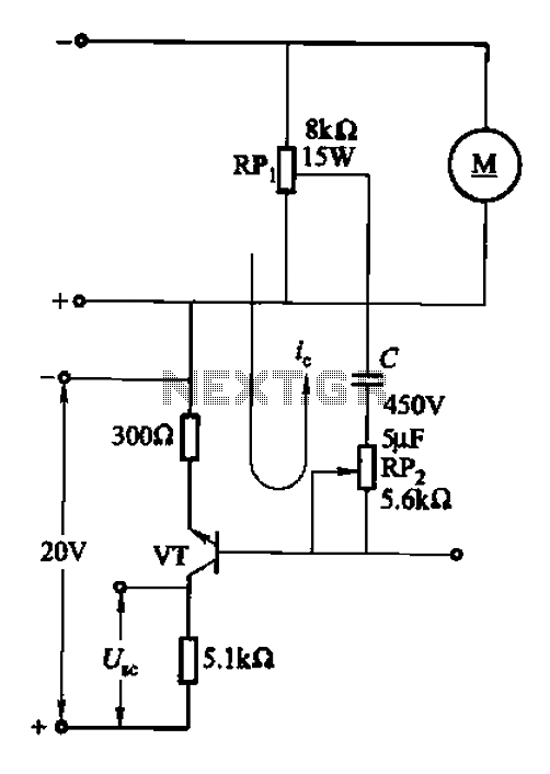
The voltage differential circuit operates by comparing the input voltage levels and generating a corresponding output that mitigates the oscillations. This is achieved through a differential amplifier configuration that amplifies the difference between the two input signals, allowing for precise control over the output. The use of a thyristor in this configuration provides a means to adjust the conduction angle, which directly influences the power delivered to the electric machine. By controlling the conduction angle, the circuit can effectively smooth out fluctuations in speed, leading to a more stable operation.
The removal of the potentiometer RPi from the motor speed feedback path is a significant modification. This change ensures that the feedback loop is not influenced by variable resistance, which can introduce additional noise and instability into the system. Instead, the voltage input terminal RP2 is utilized to provide a more stable reference point for the differential circuit, enhancing the overall performance of the feedback loop.
In summary, the implementation of a voltage differential or speed differential circuit in conjunction with a negative feedback mechanism is an effective strategy for reducing oscillations in electric machine speed control. This approach not only stabilizes the system but also improves the responsiveness and accuracy of the motor control, ensuring efficient operation across varying load conditions.After adding the negative feedback circuit, since the adjustment object and inertial measurement feedback link, prone to oscillation. To this end the use of electric voltage di fferential or speed differential circuit to reduce or eliminate oscillations that act as dynamic correction. Circuit aULk] FIG 16-34. Remove from the potentiometer RPi motor speed to reflect changes in voltage, the RP2, group C as a voltage input terminal of the differential transistor circuit away VT amplifier, thereby changing the thyristor conduction angle, to reduce the electric machine speed changes.
Related Circuits
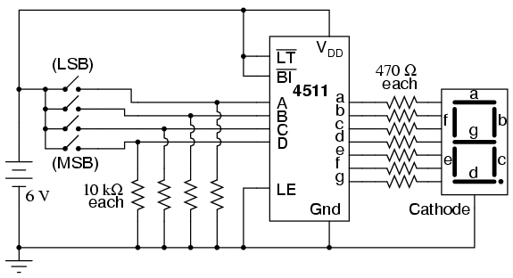
Digital circuits are circuits that handle signals restricted to binary states of zero and a maximum value. This is in contrast to analog circuits, where signals can vary continuously within the limits set by power supply voltage and circuit...
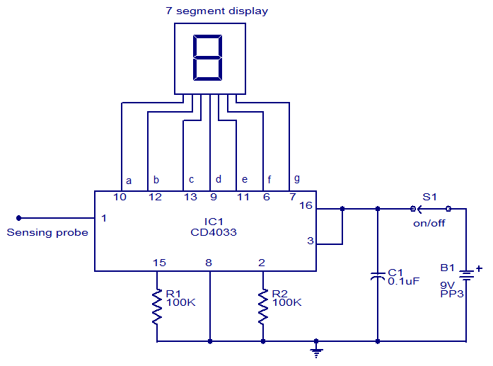
This circuit is designed to test the presence of mains voltage without direct electrical contact with the mains line. The core component of this circuit is the CMOS IC CD4033, which features a five-stage decade Johnson counter and an...
The electronic switch consists of the CK-4 type magnetic control switch and the components VT1, R1, and R2. When the bathroom door is closed, the permanent magnet ZT and the reed switch GA come into proximity, which separates the...
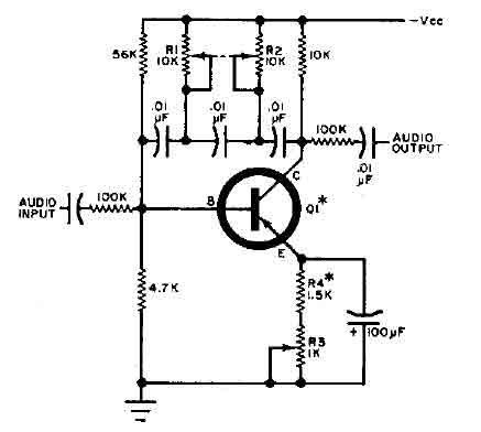
This circuit is designed for selective tuning adjustments between two closely spaced audio tones. The frequency is determined by the values of the capacitors and resistors in the feedback circuit connecting the collector and base of transistor Q1. With...
The Mark3 version of the Infrared extender is specifically designed to control appliances that utilize high-frequency modulated infrared remote signals. The Mark3 Infrared extender functions as a bridge between a standard infrared remote control and appliances that operate with high-frequency...
The circuit is a battery charging system powered by Q2, Q6, R8, and D10, which provides constant current to charge the battery. When an external power supply is present, the charging current flows through R8 and D10 to charge...
Warning: include(partials/cookie-banner.php): Failed to open stream: Permission denied in /var/www/html/nextgr/view-circuit.php on line 713
Warning: include(): Failed opening 'partials/cookie-banner.php' for inclusion (include_path='.:/usr/share/php') in /var/www/html/nextgr/view-circuit.php on line 713