
On-off Infrared Remote Control
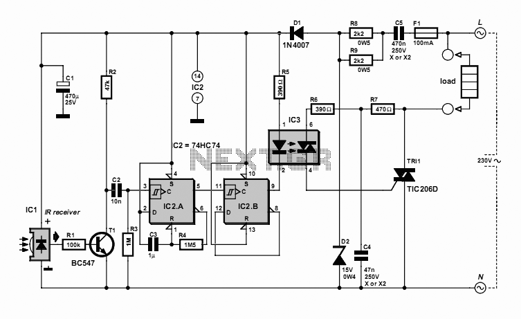
The on-off infrared remote control circuit is designed to allow users to wirelessly control electronic devices from a distance using infrared (IR) signals. This circuit typically consists of a transmitter and a receiver. The transmitter includes an infrared LED that emits modulated light signals corresponding to specific commands, while the receiver is equipped with a photodiode or phototransistor that detects these signals.
The circuit operates by converting the user's input commands into a series of binary signals, which are then transmitted as infrared light pulses. The modulation of the IR signals ensures that the receiver can differentiate between different commands, allowing for precise control over the connected devices.
In a typical application, the transmitter circuit may include a microcontroller to process button presses from a keypad or interface. This microcontroller generates the appropriate pulse-width modulation (PWM) output to drive the IR LED. The receiver circuit, on the other hand, is usually connected to a microcontroller or a simple relay driver circuit that interprets the received signals and activates the corresponding output, such as turning a device on or off.
For enhanced functionality, additional components such as capacitors, resistors, and diodes may be integrated into the circuit to filter noise and stabilize the operation. The power supply for both the transmitter and receiver can be provided by batteries or an external power source, depending on the design requirements.
Overall, the on-off infrared remote control circuit exemplifies a practical application of infrared technology in consumer electronics, providing convenience and ease of use in everyday devices.On-off Infrared Remote Control Circuit Most homes today have at least a few infrared remote controls, whether they be for the television, the video recorder, the stereo, etc. Despite that fact, who among us has not cursed the li.. 🔗 External reference
Related Circuits
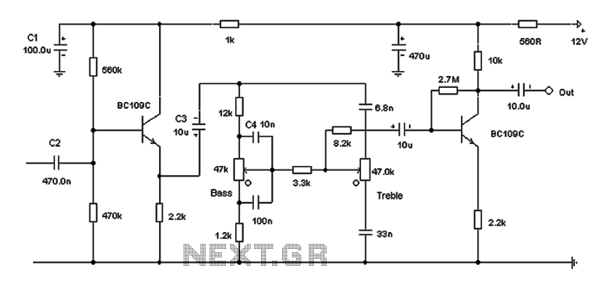
Based on the classic Baxendall tone control circuit, this design offers a maximum cut and boost of approximately 10 dB at 10 kHz and 50 Hz. Since the controls are passive, the final transistor provides a slight boost. The...
Develop a device that operates independently of gasoline, is user-friendly, can serve as a backup energy source, and allows for sharing the construction process with others. The instructional video series is structured similarly to a previous large project that...
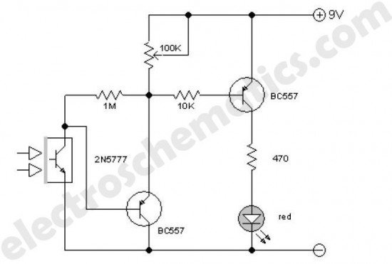
This enhanced infrared detector is designed for use with commercial infrared remote control handsets. This compact circuit is effective for quick go/no-go applications. The infrared detector circuit is engineered to respond to signals emitted by infrared remote control devices, commonly...
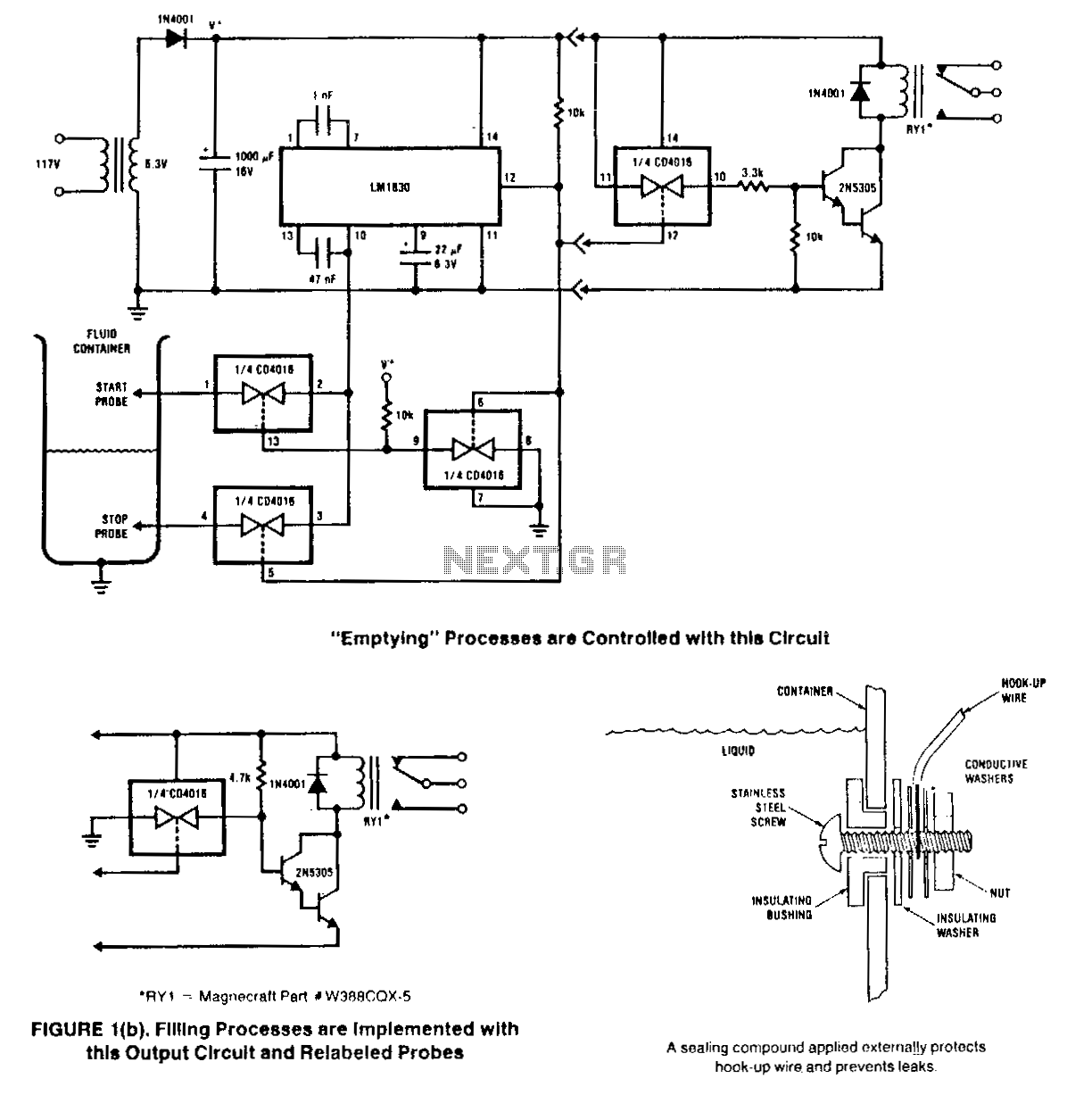
This circuit is designed to detect the presence or absence of aqueous fluids. An AC signal generated on-chip is passed through two probes within the fluid. A detector determines the presence of the fluid by using the probes in...

The proposed remote control circuit can be utilized to control any electrical device within a range of 100 meters. This concept involves modifying an existing remote bell unit circuit, making the process straightforward. However, the construction aspect necessitates electronic...
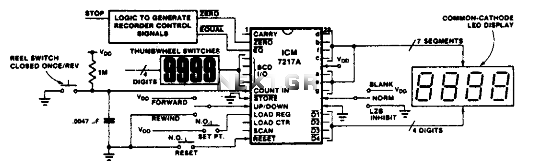
This circuit illustrates various applications of up/down counting for monitoring dimensional position. In the tape recorder application, the LOAD REGISTER, EQUAL, and ZERO outputs are utilized to control the recorder. To ensure the recorder stops at a specific point...