
One battery fast charge circuit
The described charging circuit employs a sophisticated method to optimize battery performance by utilizing a rapid charge and discharge cycle. The system is designed to monitor the battery voltage continuously and respond accordingly to prevent excessive polarization, which can lead to reduced battery lifespan and efficiency. The integration of a potentiometer allows for fine-tuning of the discharge time interval, adapting the charging process to the specific state of the battery.
In practical terms, this circuit can be implemented using a microcontroller or a dedicated battery management IC that can handle the necessary voltage and current levels. The circuit would typically include components such as a voltage sensor to detect the battery voltage, a current sensor to monitor the charging and discharging currents, and a relay or MOSFET to control the charging path.
The charging algorithm can be programmed to initiate charging at a high current until the voltage reaches the polarization point, at which point the system would switch to a discharge mode to reduce voltage and alleviate polarization. Following this, the system would resume charging at a high current, ensuring that the battery is charged efficiently without overheating.
Thermal management is also an essential aspect of this design, as rapid charging can generate heat. Adequate heat sinking or cooling mechanisms should be incorporated to maintain optimal operating temperatures.
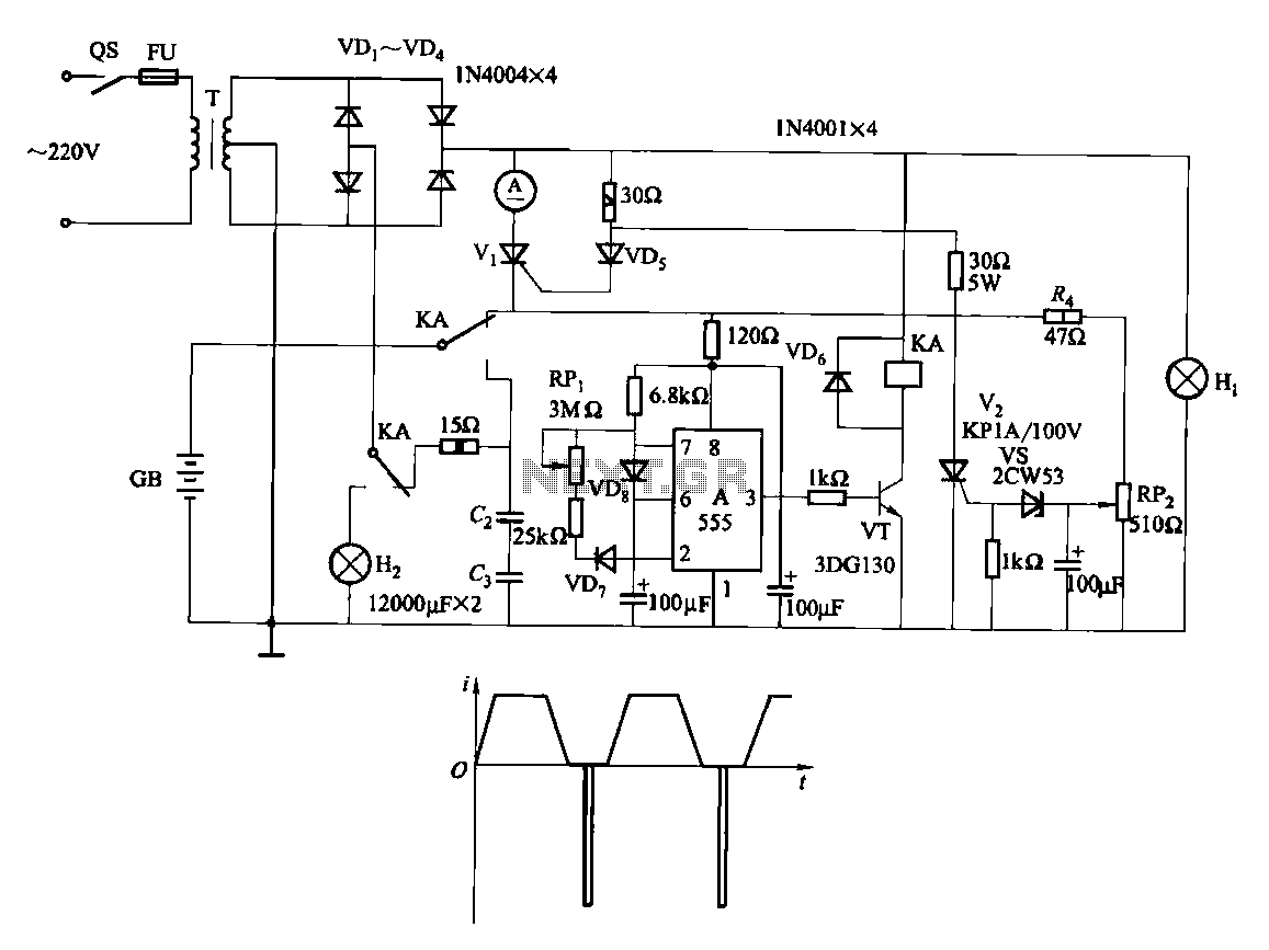
Overall, this advanced charging circuit not only improves charging efficiency and speed but also extends the life of the battery, making it suitable for applications such as electric vehicles and high-capacity battery systems.Fast and efficient charging is higher than conventional charging ten times to several times the current charge. When the battery voltage rises to a predetermined value when (va porization point), polarization within the cell is more serious, it should stop charging. And then let the battery instantaneous large current discharge, the battery voltage drops rapidly, quickly disappeared polarization, and then use a large current continues to charge, so the anti- complex circulation. When such a charging method, temperature is not high, charging speed, efficiency up to 90%, can improve the storage life of the pool.
Fast-charge, original charging time can be shortened to about 20h 1-2h, and can save energy by 20% - 25%. Circuit is shown. It can be used as 12V car battery. Adjustment potentiometer RPi, change the discharge time interval. Pay special attention to the charging and discharging time interval to be transferred to the battery in the electrochemical reaction rate to adapt.
When the battery voltage is low, the electrochemical reaction quickly, so a shorter time interval some; while the battery close enough, the interval should be longer.
Related Circuits
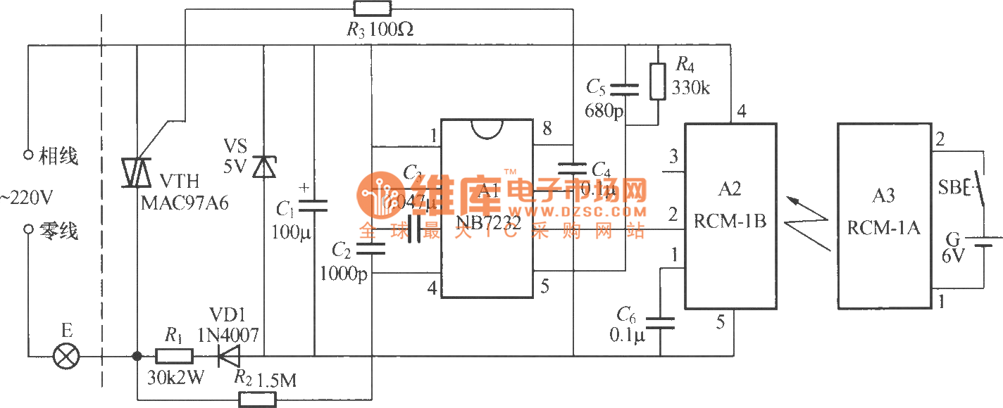
The diagram above illustrates a radio remote control dimmer circuit. This circuit utilizes a micro radio transmit/receive module in conjunction with a light modulation ASIC, resulting in a compact and easily producible design. It operates reliably and features a...
This sound frequency meter circuit is simple to build and can be constructed in a portable format. It can measure frequencies with a minimum level of 10 mV. The sound frequency meter circuit is designed to provide an effective and...
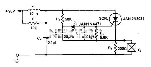
The LRC input network limits the anode dv/dt to a safe value below 30 V/μs. Rl provides critical damping to prevent voltage overshoot. While a simple RC filter section could be used, the high current required by the squib...
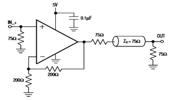
The diagram below illustrates a typical operating circuit for the video line driver using the IC4030/4031 schematic. It incorporates the MAX4030E/MAX4031E, which are unity-gain stable operational amplifiers that offer high-speed performance, rail-to-rail outputs, and 15kV ESD protection, as stated...
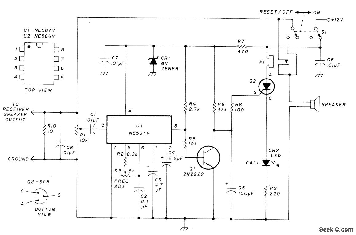
This circuit allows for monitoring a local VHF FM repeater for calls from friends without the need to listen to the background chatter or noise from the repeater. Its operation mimics that of Motorola paging units, where a special...
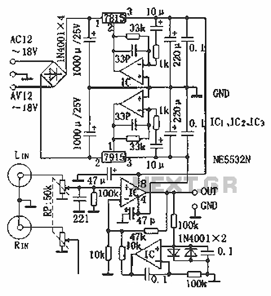
Hi-fi headphones possess a wide frequency response and low distortion, making them incomparable to desktop Hi-Fi audio systems, particularly when compared to some branded headphones and even high-quality speakers. High-fidelity headphones are designed for music listening, offering high resolving...
Warning: include(partials/cookie-banner.php): Failed to open stream: Permission denied in /var/www/html/nextgr/view-circuit.php on line 713
Warning: include(): Failed opening 'partials/cookie-banner.php' for inclusion (include_path='.:/usr/share/php') in /var/www/html/nextgr/view-circuit.php on line 713