
Sound Frequency Meter Circuit
The sound frequency meter circuit is designed to provide an effective and user-friendly means of measuring audio frequencies in a compact and portable configuration. The circuit typically employs a microphone to capture sound waves, which are then converted into electrical signals. The primary function of the circuit is to measure sound frequencies, starting from a minimum input voltage level of 10 mV, ensuring it can detect a wide range of audio signals.
Key components of the circuit may include an operational amplifier (op-amp) for signal amplification, a microcontroller or frequency counter for processing the amplified signals, and a display unit, such as an LCD or LED, to present the frequency readings. The op-amp boosts the input signal from the microphone, allowing for better detection and measurement of lower frequency sounds.
The microcontroller processes the amplified signal to determine the frequency by counting the number of cycles within a specific time frame. This data is then sent to the display unit, where users can easily read the frequency measurement. Additionally, the circuit can be designed with a portable power supply, such as batteries, ensuring that it can be used in various environments without the need for a fixed power source.
In terms of construction, the circuit can be laid out on a small printed circuit board (PCB) to facilitate ease of assembly and portability. Components should be selected for their compact size and low power consumption to maintain the circuit's portability. Proper shielding and grounding techniques should also be employed to minimize noise and ensure accurate frequency measurements.
Overall, the sound frequency meter circuit is a valuable tool for applications requiring frequency analysis, such as audio engineering, music production, and sound design, making it an essential addition to the toolkit of professionals in the field.This sound frequency meter circuit is simple to build and can be constructed in a portable format. In can measure frequencies with a minimum level of 10 mV. 🔗 External reference
Related Circuits
This circuit generates a two-tone effect similar to the sound of a cuckoo. It can be utilized for doorbells or other applications due to its integrated audio amplifier and loudspeaker. When used as a sound effect generator, it can...
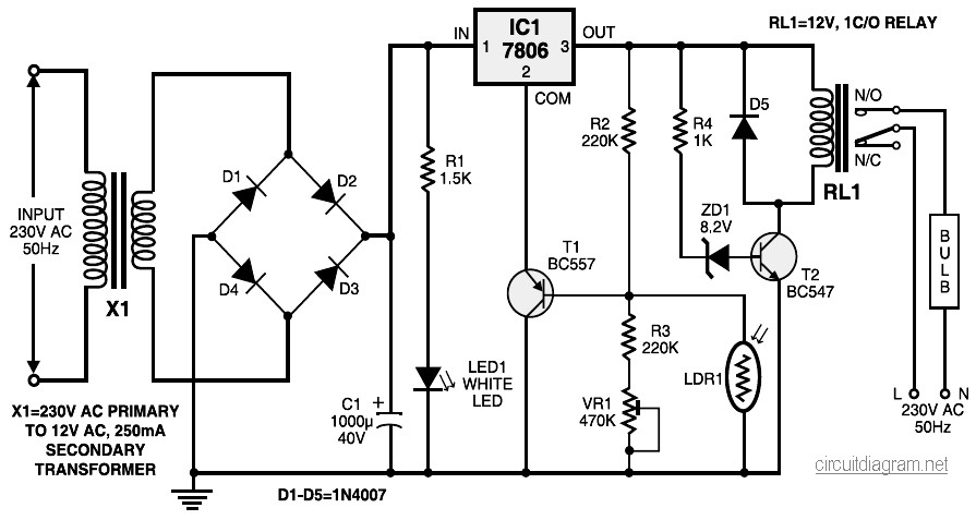
During nighttime, when no light falls on LDR1, it offers a high resistance at the base junction of transistor T1. Consequently, the bias is significantly reduced, and T1 does not conduct. This effectively removes the common terminal of IC1...
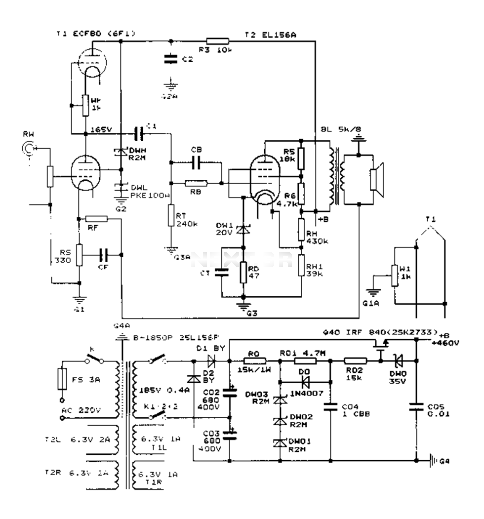
The Danji mellow sound is characterized by its transparent and natural quality, offering a sweet and sincere listening experience that is tireless over long durations and rich in humane color. Tube amplifiers have become an audiophile's companion and are...
With the help of a simple ceramic piezoelectric detector, it is possible to assemble an interesting and useful impact sensor unit, which can be used to detect... An impact sensor unit utilizing a ceramic piezoelectric detector operates by converting mechanical...
The piezo diaphragm can originate from a music card, and if two or three diaphragms are available, they can be connected in parallel, as illustrated in the diagram, to observe their impact on the output frequency. The only component...
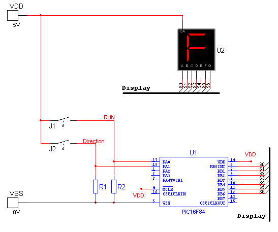
National Instruments Multisim now features microcontroller unit co-simulation capabilities, enabling the inclusion of a microcontroller, programmed in assembly or C code, within SPICE-modeled circuits. The MCU functionality in Multisim allows students, educators, and professional users to program MCUs in...
Warning: include(partials/cookie-banner.php): Failed to open stream: Permission denied in /var/www/html/nextgr/view-circuit.php on line 713
Warning: include(): Failed opening 'partials/cookie-banner.php' for inclusion (include_path='.:/usr/share/php') in /var/www/html/nextgr/view-circuit.php on line 713