
One-IC two-tones Siren
This circuit utilizes several integrated circuits (ICs) to generate sound effects suitable for various applications, particularly in children's toys and vehicles. The primary components include operational amplifiers configured as oscillators, which create distinct sound patterns. The use of switch SW1 allows for the selection between two sound modes: a dual-tone siren and a traditional siren sound.
The dual-tone sound is generated by the interaction of IC1A and IC1B, which are configured to operate at different frequencies, creating a characteristic sound that mimics emergency vehicles. The frequency of oscillation can be fine-tuned by adjusting the values of the capacitors and resistors associated with these ICs.
When the circuit is switched to the old siren mode, pressing P1 activates IC1C and IC1D, which are configured to produce a frequency that ramps up and then down, simulating a classic siren effect. This feature adds an element of fun and realism to the device.
The output sound is delivered through a loudspeaker driven by Q1, a transistor that amplifies the audio signal. It is essential to select a loudspeaker of appropriate size to ensure that the sound produced is both clear and loud enough to be heard over ambient noise. Proper enclosure of the loudspeaker can enhance sound quality and projection.
The circuit is designed to operate with minimal power consumption, especially when the old siren mode is selected. This feature is particularly advantageous for battery-powered applications, as it extends the operational life of the device. Overall, this circuit provides an engaging auditory experience for children while being versatile enough for different applications in toys and models.This circuit is intended for children fun, and is suitable to be installed on bicycles, battery powered cars and motorcycles, but also in models and other games. With SW1 positioned as shown in the circuit diagram it reproduces the typical dual tone sound of Police or Fire-brigade cars, by the oscillation of IC1A and IC1B gates.
With SW1 in the ot her position, the old siren sound increasing in frequency and then slowly decreasing is reproduced, by pushing on P1 that starts oscillation in IC1C and IC1D. The loudspeaker, driven by Q1, should be of reasonable dimensions and well encased, in order to obtain a more realistic and louder output.
Tone and period of the sound oscillations can be varied changing the values of C1, C2, C5, C6 and/or associated resistors. There is no power switch: leave SW1 in the low position (old-type siren) and the circuit consumption will be negligible.
🔗 External reference
Related Circuits
This circuit is designed for children's entertainment and can be installed on bicycles, battery-powered cars, motorcycles, as well as models and various games and toys. When switch SW1 is positioned as indicated in the circuit diagram, it generates the...
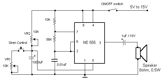
The circuit diagram of an electronic siren based on the NE555 timer produces a sound similar to that of a factory siren. The NE555 timer IC functions as an astable multivibrator with a center frequency of approximately 300 Hz....
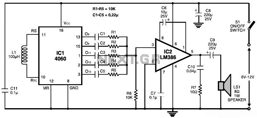
This document presents a simple schematic of a multitone siren alarm circuit. The multitone siren is effective for reverse horns, burglar alarms, and various other applications. It generates five distinct audio tones, making it significantly more attention-grabbing than a...
The sound produced mimics the rise and fall of an American police siren. When first powered on, the 10µF capacitor is discharged, and both transistors remain off. Upon pressing the push button switch, the 10µF capacitor begins to charge...
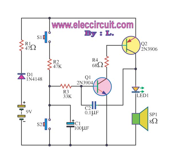
The siren circuit plays a crucial role in various alarm systems, including emergency alerts, burglar alarms, fire alarm circuits, timers, and sensor controls. Without these circuits, it would be impossible to recognize the intended functionality. The operation of the...
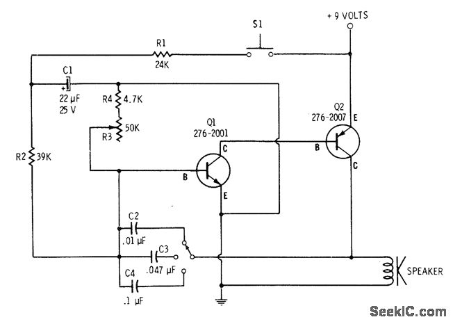
The tone is adjustable through a multiposition switch that changes capacitors in the oscillator circuit. The speed, or rate of frequency change, of the siren is controlled with resistor R3. A 4700-ohm resistor is placed in series with R3...
Warning: include(partials/cookie-banner.php): Failed to open stream: Permission denied in /var/www/html/nextgr/view-circuit.php on line 713
Warning: include(): Failed opening 'partials/cookie-banner.php' for inclusion (include_path='.:/usr/share/php') in /var/www/html/nextgr/view-circuit.php on line 713