
Single-junction transistor a phase-shift trigger circuit
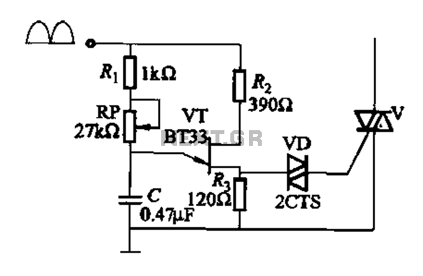
The circuit in Figure 16-29 (b) employs a programmable unidirectional transistor (PUT) as the primary triggering device for a TRIAC. The PUT is characterized by its ability to control the conduction angle, which is essential for applications requiring precise power control, such as in transfer press operations.
In this configuration, resistor R2 is critical as it helps establish the necessary trigger voltage for the PUT. The output from the circuit is connected to the gate of the TRIAC, allowing it to conduct current when the PUT is activated. The conduction angle can be adjusted using the potentiometer RP, which alters the timing of the trigger signal applied to the TRIAC.
The adjustment of the conduction angle directly influences the power delivered to the load, enabling fine-tuning of the operational characteristics of the transfer press. This feature is particularly useful in applications where varying the power level is necessary for different materials or processes. By manipulating the resistance of RP, the user can achieve optimal performance and efficiency in the operation of the transfer press, making this circuit a versatile solution in industrial settings.
Overall, the integration of the PUT in conjunction with the TRIAC and adjustable components provides a robust mechanism for controlling power in time-sensitive applications, ensuring that the system can adapt to various operational requirements.Figure 16-29 (a) of the trigger output via a resistor R2; FIG 16J29 (b) for the introduction of programmable single-junction transistor PUT trigger circuit. Adjustment potentio meter RP, can change the TRIAC conduction angle, to achieve transfer press purposes.
Related Circuits
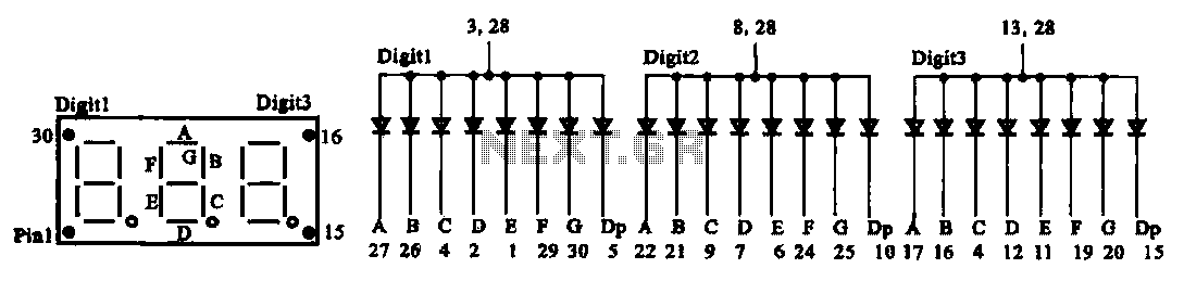
The document presents two types of digital display circuits. The first type (a) utilizes a common anode circuit configuration, while the second type (b) employs a common cathode circuit structure. The common anode display circuit configuration consists of multiple light-emitting...
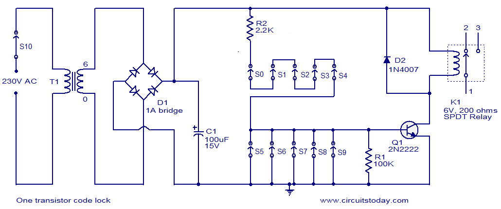
This is a simple electronic code lock circuit that can be easily constructed. The circuit consists of one transistor, a relay, and several passive components. Its simplicity does not compromise performance, and it functions effectively. The circuit operates as...
This network wiring tester consists of two components: a transmitter unit, which is powered and installed at the network's starting point, and a passive receiver unit that can be moved from socket to socket. Both units contain eight LEDs,...
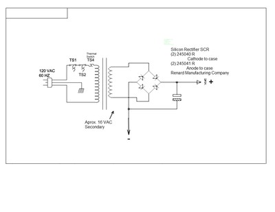
This document outlines a simple circuit diagram for a charger, utilizing a transformer, two SCRs, a capacitor, a heat sink, and a case for assembly. The circuit is designed for charging lead-acid batteries and can function even without the...
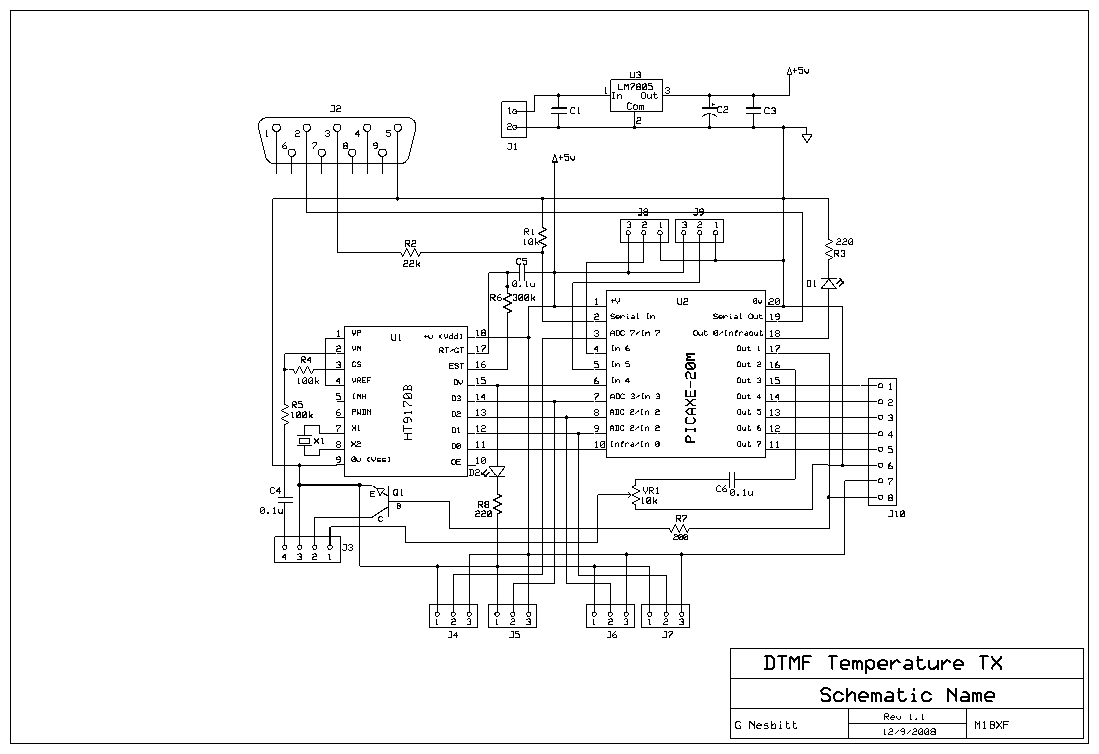
Remotely check the temperature of various items, specifically the repeater site at GB3PY. This system utilizes a radio to receive requests for the current temperature and sends the results back to the user. Requests are made using DTMF tones,...
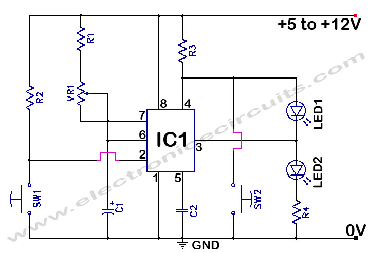
The 555 Timer Time Delay Circuit uses LEDs to visually indicate the status of the circuit at any moment. The operation begins when the reset switch, SW2, is activated. The 555 Timer is a versatile integrated circuit widely used for...