
It uses NAND gate transistor and humidity control circuit
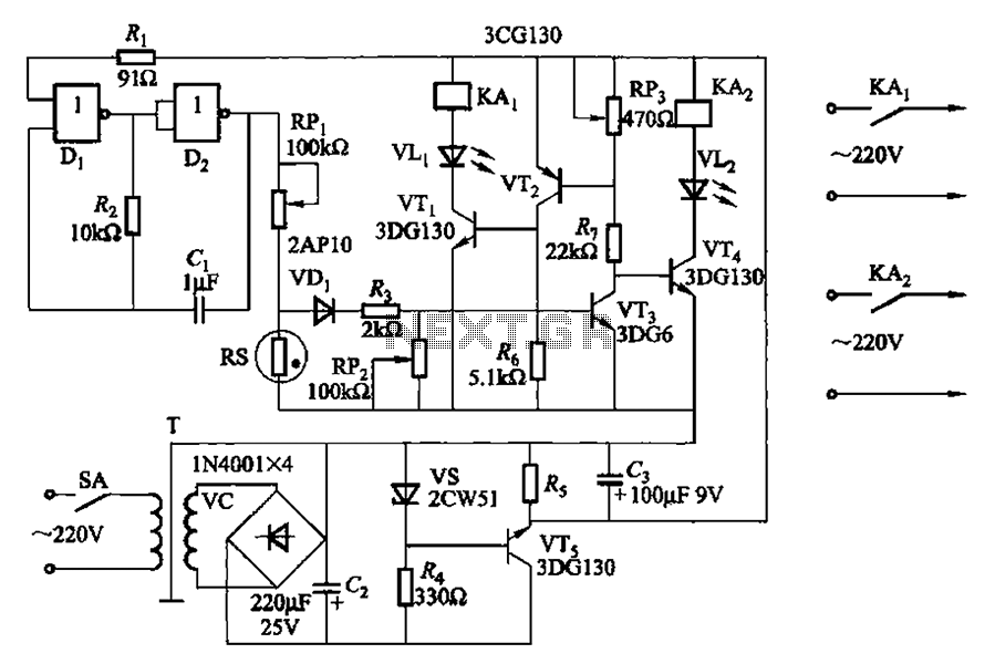
The described circuit utilizes two NAND gates configured to create a self-oscillating multivibrator. The oscillation frequency of 2.5 Hz is determined by the time constants of the resistors and capacitors in the circuit, specifically through Rz and the capacitors (C1, etc.). The output of this multivibrator generates a square wave signal with an amplitude of 4 V, which can be used to trigger further actions in the humidity control system.
The humidity control mechanism is based on the resistance changes in the humidity sensor element (RS). This sensor's resistance decreases as humidity increases, providing a feedback mechanism to the control circuit. The transistors (VT1 to VT4) are used to amplify the control signals from the NAND gates, allowing the circuit to control the relays effectively.
Relay KA2 is responsible for disconnecting the dryer when the humidity falls below the set threshold. The potentiometer (RPi) allows for fine-tuning of this threshold, enabling the user to adjust the desired humidity level. When humidity levels rise sufficiently, relay KA1 is activated to turn off the humidifier, preventing over-humidification.
This feedback loop ensures that the indoor environment remains stable and within the desired humidity range. The design is efficient and effective for maintaining optimal humidity levels, making it suitable for various applications, including greenhouses, indoor gardens, or any environment where humidity control is critical. The use of NAND gates and transistors in this circuit showcases a practical application of digital logic in analog control systems. By two NAND gates Di, Dz and resistor Rz, capacitors Cl etc. RC self-excited multivibrator oscillation frequency 2. 5Hz, the oscillation amplitude is 4V. Using as probe tempera ture humidity resistance RS element. VTi ~ VT4 composed by transistors control circuit. When the humidity drops to the set value (adjusted by potentiometer RPi), relay KA2 release, cut off the power supply dryer; at the same time, KAi pull, turn the humidifier off. When the humidity rises, RS resistance decreases when the humidity reaches the set value. KA2 pull, repeat the process, so that the indoor humidity is maintained around the set value.
Related Circuits
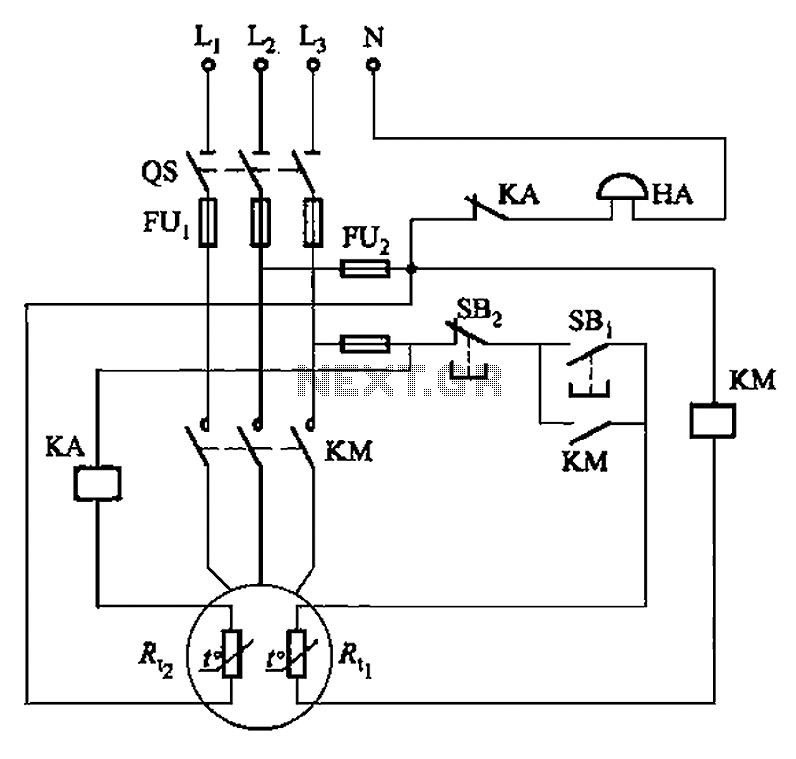
The circuit illustrated in Figure 4-2 employs two thermal resistors. One, designated as Rc, functions as overload protection, while the other, labeled Rt, serves as an alarm. The circuit in question integrates two thermal resistors to monitor temperature changes and...
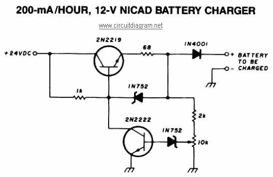
A 12V NiCAD battery charger circuit with a charging rate of 200mA per hour. This circuit initially charges the battery at 75mA until it reaches a full charge, after which the current is reduced to a trickle rate. The...
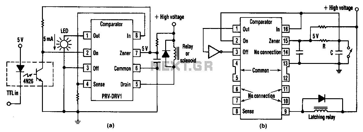
At half brightness, the lamp current is pulsed on and off by the voltage developed across the resistor and capacitor at the current-sense output. The current-sense output detects the lamp current. A basic pulse-width modulation (PWM) lamp-brightness control circuit...
This is a game timer circuit diagram. When the game timer is reset, two actions must occur: the 4017 counter must return to zero, and the 4060... The game timer circuit utilizes the 4017 decade counter and the 4060 binary...
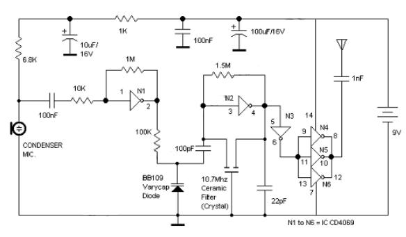
Logic Gates FM Transmitter Circuit Electronic Circuit Schematic Wiring Diagram. The FM transmitter circuit utilizing logic gates is a fundamental electronic design that operates by modulating a carrier frequency with an audio signal. This circuit typically consists of various logic...
The LM317T is an adjustable three-terminal positive voltage regulator that can supply over 1.5 amps with an output voltage range of 1.25 to 37 volts. It features built-in current limiting and thermal shutdown, making it highly reliable and resistant...