
One of the positive and negative brake circuit to operate energy
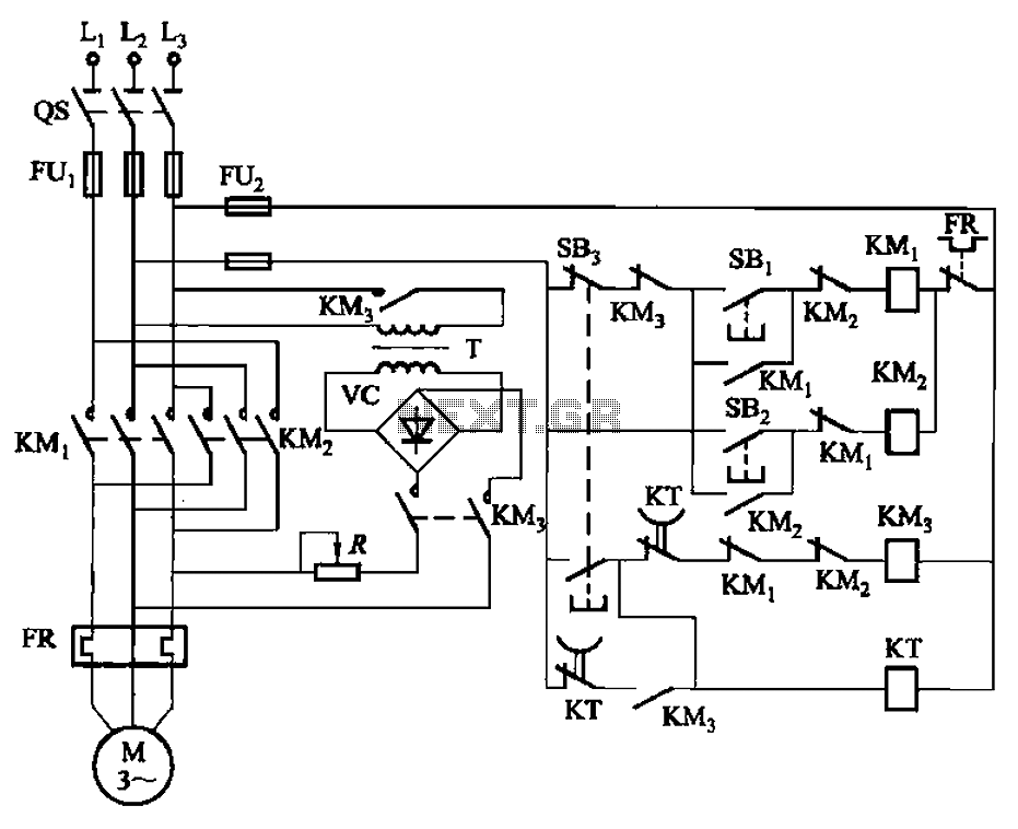
The automatic control circuit for dynamic braking is designed to enhance the efficiency and safety of electric motor operations. The time relay (KT) serves as a critical component that determines the duration of the braking action, ensuring that the motor can decelerate smoothly without causing mechanical stress or excessive wear.
The step-down transformer (T) is employed to reduce the input voltage to a level suitable for the operation of the bridge rectifier. This transformer ensures that the rectified output is compatible with the requirements of the dynamic braking system. The single-phase bridge rectifier converts the alternating current (AC) output from the transformer into direct current (DC), which is necessary for the effective operation of the braking mechanism.
The inclusion of start (SBi) and stop (SB3) buttons allows for manual control of the braking process, enabling the operator to initiate or cease braking as needed. The reverse start (SB2) and stop buttons facilitate the operation of the motor in reverse, providing flexibility in applications where reversing the motor's direction is required.
Overall, this circuit configuration ensures a reliable and efficient method for controlling dynamic braking in electric motors, contributing to improved operational performance and safety in various applications. Circuit shown in Figure 3-144. The circuit for the automatic control of dynamic braking circuit using the time relay KT control system up time, dynamic braking power using the step-down transformer T, single-phase bridge rectifier. Figure, SBi and SB3 respectively positive start and stop button, SB2 and reverse S Island start and stop buttons.
Related Circuits
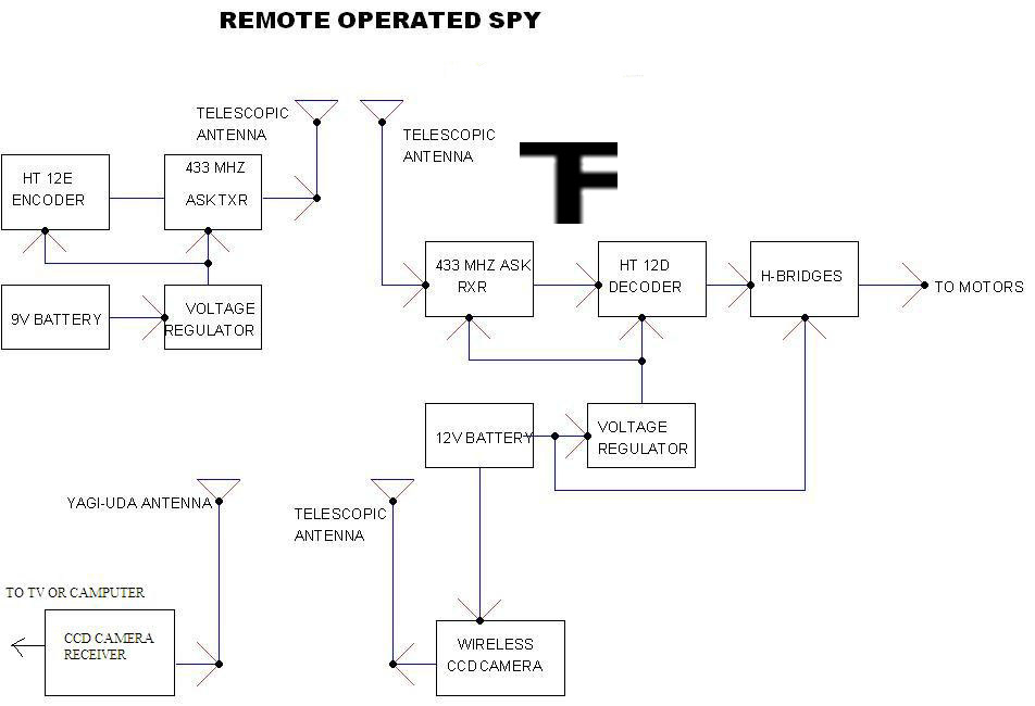
A robot that operates when you send messages through your phone. Your mobile device serves as the remote controller for the robot. This means that if the robot is in London and you are in Mumbai, you can still...
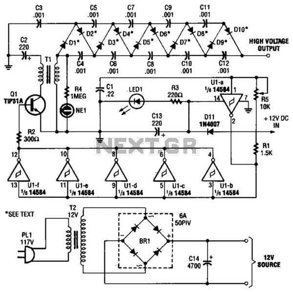
In the miniature high-voltage DC generator, the circuit receives input from a 12 V DC power supply, which is amplified to produce a 10,000 V DC output. This process induces a pulsating signal of opposite polarity in the secondary...
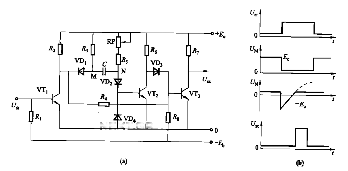
The circuit described is a discharge delay circuit that offers a longer delay compared to a standard rechargeable delay circuit, while also maintaining relatively high accuracy. The schematic diagram illustrates the input and output waveforms. Typically, when there is...
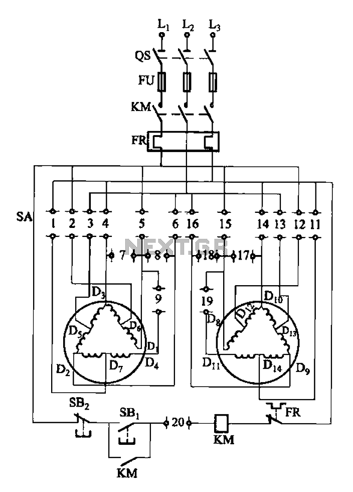
The 3-119 circuit shown in the figure combines switch SA to realize the stator windings, specifically the 2, Y, and 2Y connections, which correspond to the motor speed n1. The 3-119 circuit is designed to facilitate the control of motor...

All of ACC's repeater and remote base products support the control of synthesized remote base transceivers. One form of frequency control supported is compatible with transceivers using thumbwheel frequency selection. The controllers supply BCD (binary coded decimal) formatted data...
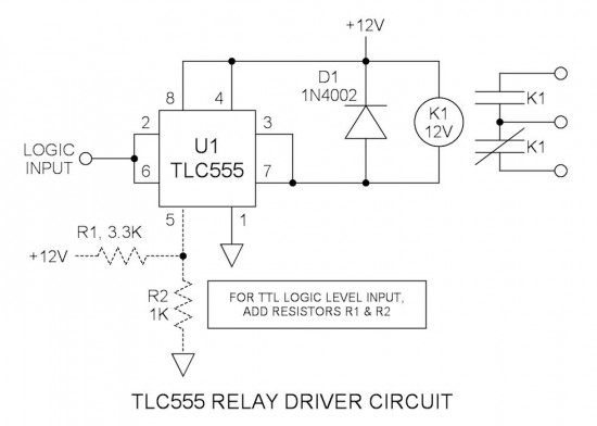
Many integrated circuits possess undocumented features or capabilities. One such example is the TLC555, which can sink a 100mA load down to 1.28V at its output (pin 3). The open-drain transistor reset (pin 7) can also sink 100mA to...
Warning: include(partials/cookie-banner.php): Failed to open stream: Permission denied in /var/www/html/nextgr/view-circuit.php on line 713
Warning: include(): Failed opening 'partials/cookie-banner.php' for inclusion (include_path='.:/usr/share/php') in /var/www/html/nextgr/view-circuit.php on line 713