
DIGITAL VOLTMETER CIRCUIT

The digital voltmeter circuit using the ICL7107 is designed to provide precise voltage measurements within a specified range. The ICL7107 is a dedicated analog-to-digital converter (ADC) that converts the analog voltage input into a digital output, which can then be displayed on a seven-segment display for easy reading.
The circuit configuration includes a few critical components: the ICL7107 ADC, a reference voltage source, a display driver, and passive components such as resistors and capacitors for stability and calibration. The power supply of ±5 V is essential for the proper functioning of the ICL7107, ensuring that it operates within its specified voltage range.
Calibration is a vital process for ensuring the accuracy of the voltmeter. By applying a known voltage of 1.2 V to the input, the user can adjust resistor R3 to calibrate the display accurately. This adjustment aligns the digital output with the actual input voltage, allowing for reliable measurements.
Switch S1 plays a crucial role in the circuit by providing flexibility in voltage reference selection. It allows the user to choose between using the internal supply voltage or an external reference voltage, enhancing the versatility of the voltmeter for different applications.
Overall, this digital voltmeter circuit is a straightforward yet effective design suitable for various electronic measurement tasks, leveraging the capabilities of the ICL7107 to deliver accurate and reliable voltage readings.A basic digital voltmeter circuit using the Harris Semiconductor ICL7107 is shown. It has a 2-V range. Calibration consists of applying a known voltage of 1.2 V to the input and adjusting R3 for a correct reading on the display. Supply is ±5 V, and S1 selects either the supply voltage or an external reference.. 🔗 External reference
Related Circuits

This is a simple basic design of a servo motor controller with a pulse generator. It utilizes the CMOS IC 7555 in astable mode to generate pulses for driving the motor. The servo motor controller circuit employs the CMOS IC...

An FM transmitter, commonly referred to as an FM transmitter, utilizes two transistors, specifically the 2N2222 model. When in operation, this FM transmitter requires a 9-volt battery for power and operates with an antenna that is less than 12...
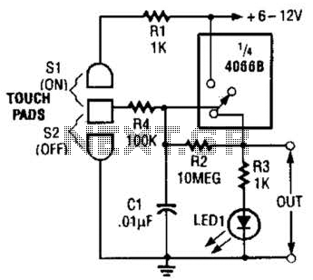
This touch-on switch can be activated through electrical means and can only be reset using a mechanical switch. When the touch terminal is activated by a finger, the SCR turns on and illuminates LED1. The circuit utilizes a silicon-controlled rectifier...
The AB763 Super Reverb is a highly regarded Fender amplifier known for its rich tone, durability, and the classic sound derived from the traditional blackface AB763 design. This design was also utilized in some silverface amplifiers produced between 1967...
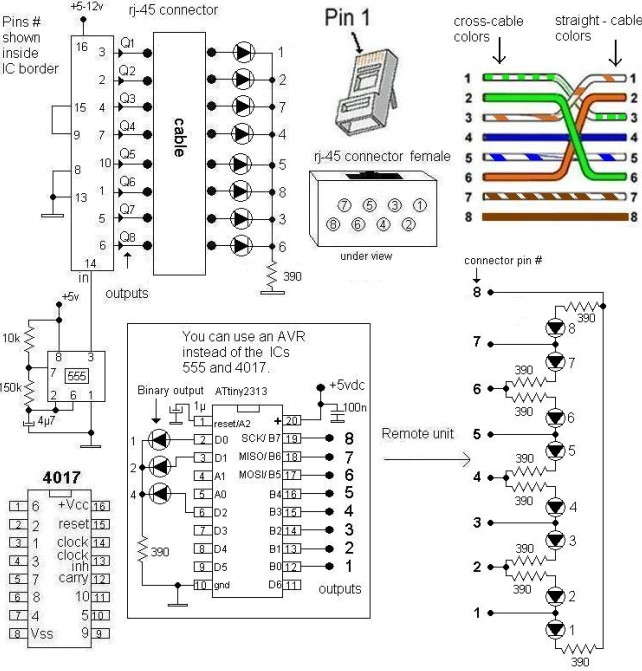
This LAN tester circuit was originally designed by Vassilis Stergiopoulos. It features two optional designs. The first design utilizes two main integrated circuits: the timer IC555 and the decade counter 4017. The second design is based on the microcontroller...

The input capacitor is used for low-frequency cut-off, with a standard value of 0.1 µF, resulting in a cut-off frequency of approximately 16 Hz. The input capacitor plays a crucial role in filtering unwanted low-frequency signals in electronic circuits. By...