
One second Audible Clock Circuit Schematic
The one-pulse-per-second clock circuit is designed for high reliability and ease of assembly. The central component, the CMOS 4024 counter/divider, is a versatile device capable of dividing input frequencies by whole numbers. This feature allows the circuit to produce a precise one-second pulse from the mains frequency with minimal external components. The high input impedance at pin #1 ensures that the circuit can be activated by very weak signals, making it suitable for various environments.
The use of diodes in the circuit serves multiple purposes, including signal rectification and protection. The arrangement of three diodes provides necessary isolation and ensures that the circuit operates correctly regardless of the mains frequency. The modification for 60Hz operation is straightforward, requiring only a simple reconfiguration of the connections.
The optional visual display, consisting of a light-emitting diode (LED) and a resistor, enhances the circuit's functionality by providing a visual indication of the one-second pulse. The choice of resistor value is crucial; for battery voltages of 9V or higher, using a 1K resistor prevents excessive current flow through the LED, ensuring longevity and consistent performance.
Overall, this circuit design demonstrates a practical approach to creating a precise timing signal suitable for various applications, from simple timers to more complex delay mechanisms. Its reliance on common components ensures accessibility for hobbyists and professionals alike, while the straightforward modifications allow for adaptability to different mains frequencies.This accurate one-pulse-per-second clock is made with a few common parts and driven from a 50 or 60 Hertz mains supply but with no direct connection to it. A beep or metronome-like click and/or a visible flash, will beat the one-second time and can be useful in many applications in which some sort of time-delay counting in seconds is desirable.
Th e circuit is formed by a CMos 4024 counter/divider chip and 3 diodes, arranged to divide the frequency of the input signal at pin #1 by 50 (or 60, see Notes). The input impedance at pin #1 is very hight, so simply touching the pin (or a short track or piece of wire connected to it) is usually enough to provide the necessary input signal.
Another way to provide an input signal consists in a piece of wire wrapped several times around any convenient mains cable or transformer. No other connection is necessary. To allow precise circuit operation in places where the mains supply frequency is rated at 60Hz, the circuit must be modified as follows: disconnect the Cathode of D1 from pin #11 of IC1 and connect it to pin #9.
Add a further 1N4148 diode, connecting its Anode to R1 and the Cathode to pin #6 of IC1: that`s all! The visual display, formed by D4 and R3 is optional. Please note that R3 value shown in the Parts list is suited to low battery voltages. If 9V or higher voltages are used, change its value to 1K. 🔗 External reference
Related Circuits
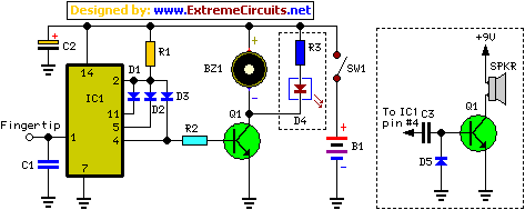
A logic pen, also known as a logic detection probe, is a commonly used tool for detecting the logic state at various points within digital circuits. The logic states in digital circuits are typically categorized into three types: a...
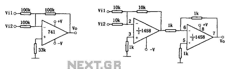
The common addition circuit is illustrated, with Figure (a) depicting the inverting adder circuit. The input-output relationship is expressed as Vo = -(Vi1 + Vi2). For phase addition, the circuit shown in Figure (b) can be utilized, with the...
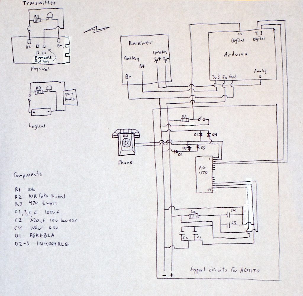
Any phone can be utilized for this project, so there is no need to worry about obtaining the same model as mentioned. If an antique Bakelite phone is chosen, basic restoration steps include cleaning it with a rag dampened...

This is an application circuit for calibration known as a high voltage AC calibrator circuit. A key aspect of sine wave oscillator design is the stable control of amplitude. In this circuit, the amplitude is stabilized through servo control,...

The power controller operates from the vehicle's accessory switch, allowing the load to receive power only when the ignition key is in the "on" position. A momentary pushbutton controls a load of up to 10 A using half of...
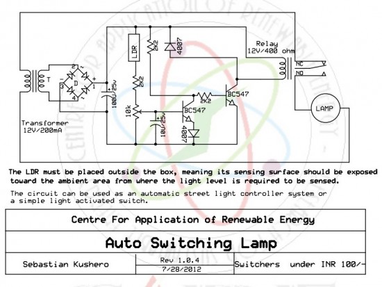
The circuit is designed to switch off a specific lamp or a group of lamps based on varying ambient light levels. Once constructed, it will turn off a lamp at dawn and turn it on at dusk. The power...
Warning: include(partials/cookie-banner.php): Failed to open stream: Permission denied in /var/www/html/nextgr/view-circuit.php on line 713
Warning: include(): Failed opening 'partials/cookie-banner.php' for inclusion (include_path='.:/usr/share/php') in /var/www/html/nextgr/view-circuit.php on line 713