
two-tone generator
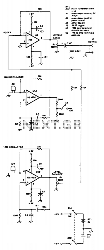
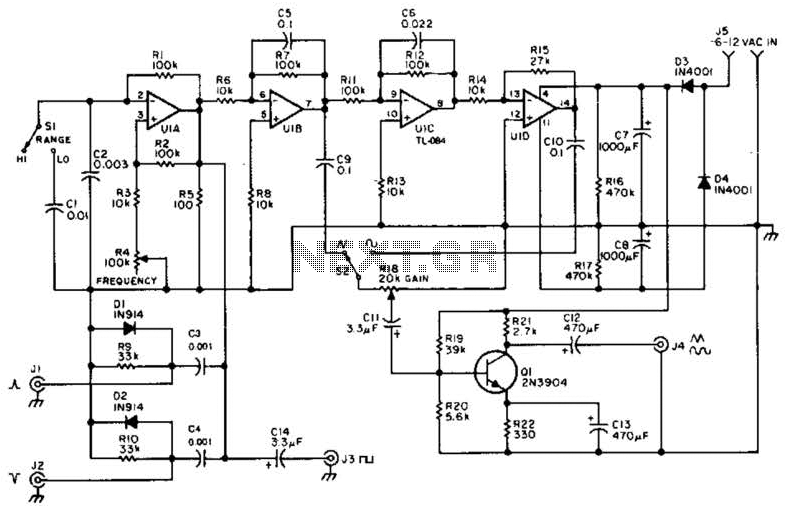
The Wien bridge oscillator is a widely used circuit for generating sine waves, characterized by its simplicity and effectiveness. In this configuration, the two 741 operational amplifiers (or the 1458 dual op-amp) play crucial roles in establishing the oscillation frequency and maintaining stability. The oscillator circuit is designed to operate within a frequency range of 500 to 2000 Hz, ensuring that the selected frequencies do not exhibit harmonic relationships, which could lead to distortion in the output waveform.
In the circuit, the first operational amplifier, U1A, is configured to set the output level through a resistive divider network. This arrangement allows for precise control over the amplitude of the signal generated by U1A. The second operational amplifier, U1B, features an adjustable output, which is controlled by the variable resistor Rl. This adjustability is essential for fine-tuning the oscillator's performance and ensuring that the output remains stable.
The outputs from both U1A and U1B are combined in the third operational amplifier, U2, which acts as an adder with unity gain. This configuration allows for the summation of the two oscillating signals, resulting in a composite output that retains the desired characteristics of both oscillators. The final output from U2 can be adjusted further using resistor R2, providing an additional level of control over the amplitude of the output signal.
Overall, this Wien bridge oscillator design effectively utilizes operational amplifiers to generate stable sine wave outputs across a specified frequency range, making it suitable for various applications in signal generation and waveform synthesis.Two 741 operational amplifiers are used for the active element in this Wien bridge oscillator. (The 1458 is the dual version of the 741.) Frequencies of the two oscillators were chosen to fit standard component values. Other frequencies between 500 and 2000 Hz can be employed. They should not be harmonically related. The output level of U1A is set by a resistive divider, while the output of U1B is adjustable through Rl. The output of the two oscillators is combined in U2, an op-amp adder with unity gain. The output from U2 can be adjusted using R2. 🔗 External reference
Related Circuits
this tone generator can be used to control your robot. you will need to use the tone decoder for this. to widen the range, higher or lower - substitute a higher, or lower valued capacitor for c1. for frequencies...
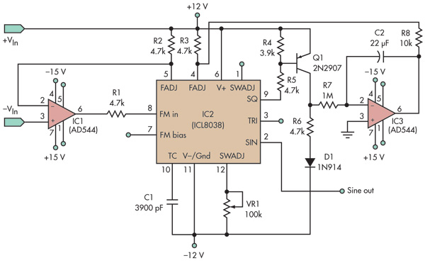
This basic voltage-controlled oscillator (VCO) and waveform generator integrated circuit (IC) circuit features a voltage follower loop (formed with IC1) and a symmetry feedback loop (IC3) designed to eliminate asymmetric duty cycles that can lead to distortion at low...
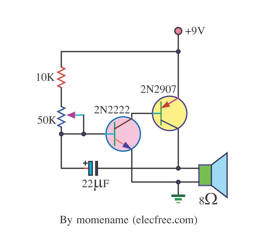
This is a simple tone oscillator generator. It uses the transistors 2N2222 and 2N2907 as the main components. The tone sound is controlled with a 50K ohm resistor (R2) and an 8-ohm speaker is utilized. The tone oscillator generator circuit...
A quad op-amp serves as the core component of this function generator. U1A produces a square wave, which is outputted to J8. J1 and J2 are pulse outputs derived from differentiating the square wave. The integrator U1B creates a...
The hobby circuit described utilizes a unique method to generate approximately 12,000 volts with a current of about 5 microamperes. It employs two silicon-controlled rectifiers (SCRs) that form two pulse generator circuits. These SCRs discharge a 0.047 microfarad, 400-volt...
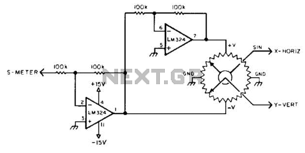
To display polar quantities, which include both the magnitude and direction of a received radio signal, a sine and cosine voltage proportional to an angle corresponding to the antenna direction is required. This setup utilizes a sine-cosine potentiometer connected...