
One transistor audio mixer
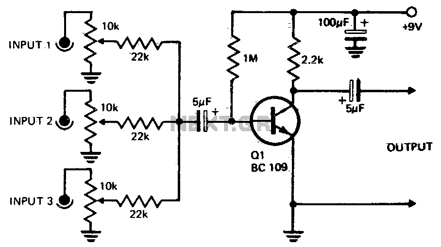
The circuit design involves a transistor amplifier configuration where three or more input signals are managed through individual level control mechanisms before being directed to the base of the transistor Q1. This arrangement allows for the adjustment of the signal levels to optimize the overall performance of the amplifier. The transistor Q1 functions as a voltage amplifier, providing a significant voltage gain of 20, which indicates that the output voltage will be 20 times greater than the input voltage, assuming ideal conditions.
In this configuration, the individual level controls can be implemented using potentiometers or variable resistors, allowing the user to fine-tune each input signal's amplitude before amplification. The base of Q1 is connected to a resistor network that helps set the biasing conditions of the transistor, ensuring it operates in the active region for linear amplification.
Additionally, proper coupling capacitors may be employed at the input stage to block any DC offset from the input signals while allowing the AC components to pass through. This will help maintain the integrity of the input signals during amplification. The collector of Q1 will be connected to a load resistor, which, in conjunction with the transistor’s characteristics, determines the output voltage swing.
The output can be further processed or sent to subsequent stages of amplification or signal processing, depending on the application requirements. Careful consideration must be given to the power supply voltage and current ratings to ensure reliable operation of Q1 and to prevent distortion or clipping of the amplified signal.Three or more inputs with individual level controls feed into the base of Q1 that provides a voltage gain of 20. 🔗 External reference
Related Circuits
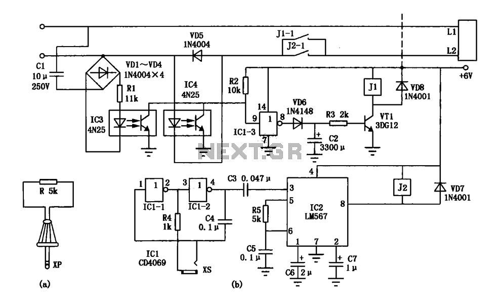
An electronic lock utilizing a telephone key, which is connected through a resistor plug, is integrated after the oscillator circuit's startup phase. The accuracy of the oscillation frequency determines whether the phone can be used for outgoing calls, while...
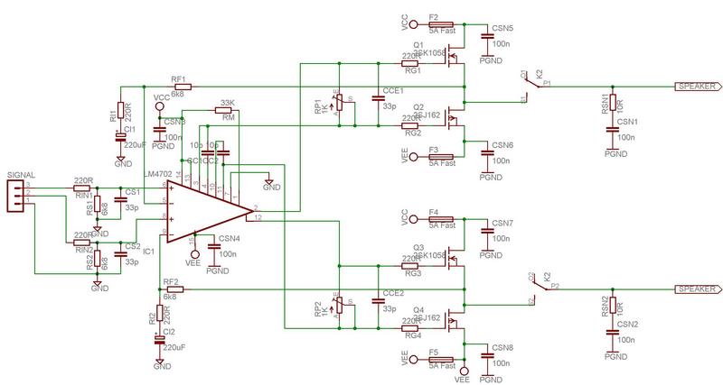
The LM4702 has been integrated into a Crown DC150 amplifier. The driver board in the Crown was damaged, but the power supply remains functional. The LM4702 is a high-performance audio amplifier IC designed for use in various audio applications, including...
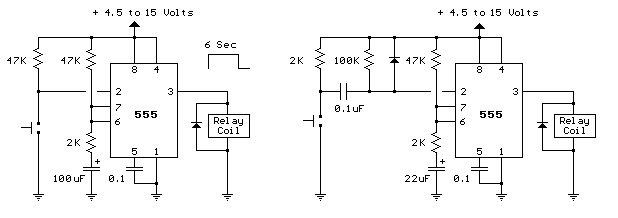
The two circuits below illustrate the application of the 555 timer to activate a relay for a specified duration by pressing a momentary normally open (N/O) push button. The circuit on the left can be used for longer time...
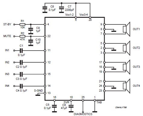
This circuit illustrates a car audio amplifier utilizing the TDA7381 integrated circuit (IC). The TDA7381 audio amplifier IC allows for the design of a straightforward 4x25 watts car radio. The TDA7381 is a high-performance audio amplifier designed specifically for automotive...
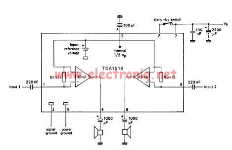
The TDA1519 circuit can deliver 2x6 watts of output power. The TDA1519 is an integrated class-B dual output amplifier housed in a 9-lead single in-line (SIL) plastic medium power package, primarily developed for car radio applications. The TDA1519 amplifier is...
This compressor will compress a 25-mV peak-to-peak (p-p) audio signal to a 20-V p-p output, maintaining input levels between 1.5 V p-p and 3.5 V p-p, with a frequency response ranging from 7 Hz to 67 kHz. It is...
Warning: include(partials/cookie-banner.php): Failed to open stream: Permission denied in /var/www/html/nextgr/view-circuit.php on line 713
Warning: include(): Failed opening 'partials/cookie-banner.php' for inclusion (include_path='.:/usr/share/php') in /var/www/html/nextgr/view-circuit.php on line 713