
1w led driver
This circuit effectively regulates the output current to safely drive high-power LEDs while accommodating variations in temperature and LED characteristics. The utilization of a buck converter topology allows for efficient energy conversion, minimizing heat generation and improving overall system reliability.
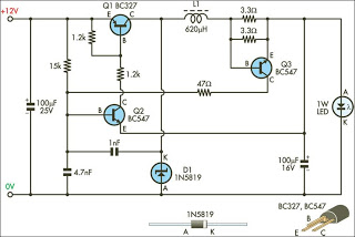
Transistor Q1 operates in a switching mode, rapidly turning on and off to control the energy delivered to the output. The inductor L1 stores energy when Q1 is on and releases it to the load when Q1 is off, maintaining a steady output current. Diode D1 ensures that current flows in the correct direction and prevents backflow when the switch is off. The output capacitor smooths the current to provide a stable voltage to the LED.
The feedback loop, which includes Q3 and the resistors, plays a critical role in maintaining the desired output current. When the output current exceeds the set threshold, Q3 activates, providing a mechanism to reduce the drive to Q1 and stabilize the output. The hysteresis introduced by the RC network connected to Q2's base prevents rapid oscillations, ensuring a stable operation without excessive flickering of the LED.
The design emphasizes the importance of selecting appropriate components, particularly the inductor and resistors, to achieve the desired performance. The choice of a toroidal inductor helps minimize electromagnetic interference (EMI), which is crucial in LED applications where flicker and noise can affect visual performance. Adjusting the output current prior to connecting the LED is essential to prevent damage, and the specified procedure ensures that the circuit is calibrated for safe operation. Overall, this circuit represents a robust solution for driving 1W LEDs with precision and efficiency.This circuit is designed to drive the 1W LEDs that are now commonly available. Their non-linear voltage to current relationship and variation in forward voltage with temperature necessitates the use of a 350mA, constant-current power source as provided by this supply. In many respects, the circuit operates like a conventional step-down (buck) swit ching regulator. Transistor Q1 is the switching element, while inductor L1, diode D1 and the 100mF capacitor at the output form the energy transfer and storage elements. The pass transistor (Q1) is switch-ed by Q2, which together with the components in its base circuit, forms a simple oscillator.
A 1nF capacitor provides the positive feedback necessary for oscillation. The output current is sensed by transistor Q3 and the two paralleled resistors in its base-emitter circuit. When the current reaches about 350mA, the voltage drop across the resistors exceeds the base-emitter forward voltage of transistor Q3 (about 0.
6V), switching it on. Q3`s collector then pulls Q2`s base towards ground, switching it off, which in turn switches off the main pass transistor (Q1). The time constant of the 15kW resistor and 4. 7nF capacitor connected to Q2`s base adds hysteresis to the loop, thus ensuring regulation of the set output current.
The inductor was made from a small toroid salvaged from an old computer power supply and rewound with 75 turns of 0. 25mm enamelled copper wire, giving an inductance of about 620mH. The output current level should be trimmed before connecting your 1W LED. To do this, wire a 10W 5W resistor across the output as a load and adjust the value of one or both of the resistors in the base-emitter circuit of Q3 to get 3.
5V (maximum) across the load resistor. 🔗 External reference
Related Circuits
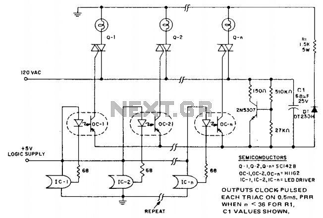
In microprocessor control of multiple loads, minimizing the cost per load is essential. A typical application is a large display that drives arrays of incandescent lamps. This circuit achieves minimal component cost per stage by utilizing optocoupler triggering of...

The circuit can be arranged in a circular format to represent the 12 hours of a clock face, with an additional 12 LEDs positioned in an outer circle to indicate 5-minute intervals within each hour. Four extra LEDs are...
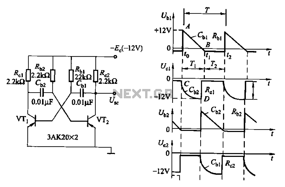
Also known as a no-shot multivibrator, this circuit is often utilized as a pulse (square wave) signal source. The astable flip-flop functions as a strong positive feedback amplifier, with its two branches coupled by an RC timing circuit, resulting...
This instruction outlines the process of converting a standard microscope that uses a light bulb to LED illumination. A mobile phone charger can be utilized as the power supply due to the significantly lower power consumption of LEDs. This...
Note first the battery to be treated at the center of the figure. It is connected to contacts of a relay. The diagram shows the relay at rest. Under these conditions the battery is in SHOCK. His pole -...
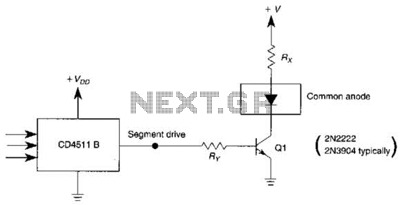
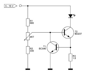
The use of a switching transistor, such as a 2N2222 or 2N3904, enables the operation of the CD4511B with a common-anode display. The transistor should be selected to provide approximately 1 mA to drive Q1, while resistor Rr must...