
ONEX HID Conversion Kit Step-by-Step Installation
To successfully integrate an HID (High-Intensity Discharge) lighting system into a vehicle, it is essential to identify the correct bulb size that corresponds to the vehicle's headlight assembly. The bulb size is crucial as it ensures compatibility with the existing socket and electrical connections. Common bulb sizes include H1, H3, H4, H7, H9, H10, H11, H13, and 9004, each designed for specific applications and vehicle models.
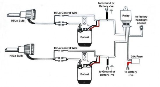
The process of selecting the appropriate bulb size typically involves consulting the vehicle's owner manual or referring to manufacturer specifications. Additionally, online databases and automotive forums can provide valuable information regarding bulb compatibility. Once the correct bulb size is identified, the installation of the HID kit can proceed, which generally includes the following components: HID bulbs, ballasts, ignitors, and wiring harnesses.
The HID bulbs operate by creating an arc between two electrodes within a gas-filled chamber, producing a bright, white light that is more efficient than traditional halogen bulbs. The ballasts play a critical role in regulating the electrical current supplied to the bulbs, ensuring optimal performance and longevity. Proper installation of the wiring harness is also necessary to facilitate a seamless connection between the vehicle’s electrical system and the HID components.
In summary, determining the correct bulb size is a vital first step in upgrading to an HID lighting system, as it directly impacts the functionality and safety of the vehicle's lighting performance.Before you purchase your HID kit, first thing you need to do is to find out what is the appropriate bulb size ( i.e. H1, H3, H4, H7, H9, H10, H11, H13, 9004. 🔗 External reference
Related Circuits

The Function Generator is essential laboratory equipment. The module described here is based on the high-quality XR2206 integrated circuit (IC). The 1Hz - 2MHz XR2206 Function Generator is capable of producing high-quality sine, square, and triangle waveforms with high...
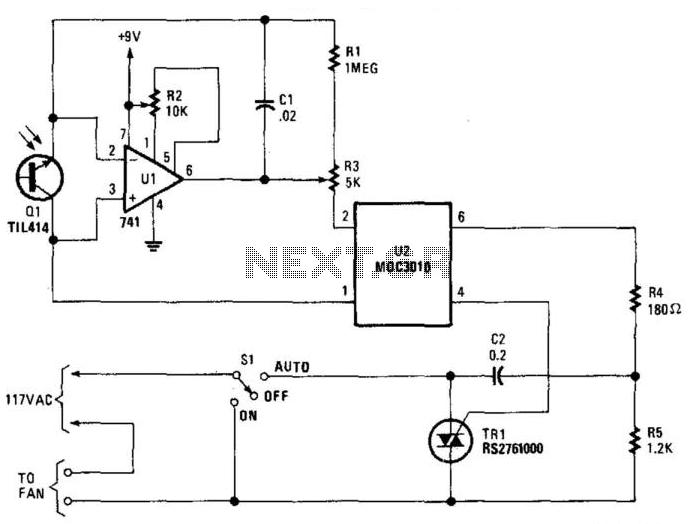
Q1 senses infrared radiation from heat sources, which causes U1 to switch on, activating optocoupler U1 and triggering TRIAC TR1. This controls a fan. The TRIAC can be sourced from Radio Shack or a 200-V, 6-A unit (C106B) can...
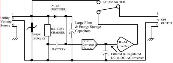
Thomas Edison developed the incandescent light bulb, which operated from a 110-volt DC source. The primary drawback of DC power was that it could only be distributed over short distances without needing to be regenerated. In the early 1900s,...
Feed the cable through a hole in the chassis to the opposite side. There, between the fan and the rear panel, the IFD board can be installed upside down. Use a thin and flexible insulating material, such as PE...
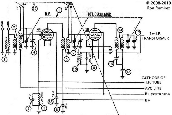
The initial step involves taking notes to indicate which wire connects to each terminal on the 36 tube socket. Remove all wires connected to the 36 tube socket. Next, drill out the rivets that secure the five-pin 36 tube...
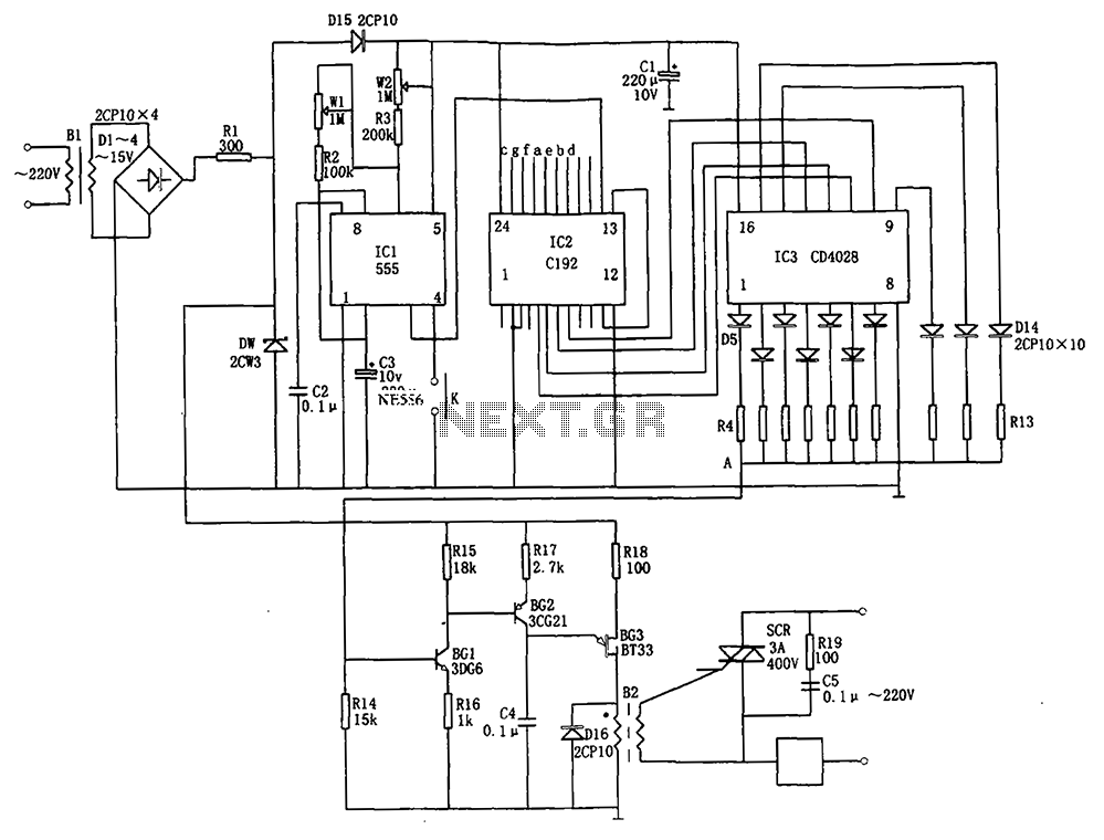
The automatic conversion circuit for wind speed control is depicted in Figure 10. This circuit consists of a clock signal generator (IC1), a counter (IC2), a decoder (IC3), a synchronous phase shifting circuit (BG1, BG2, BG3), a thyristor control...
Warning: include(partials/cookie-banner.php): Failed to open stream: Permission denied in /var/www/html/nextgr/view-circuit.php on line 713
Warning: include(): Failed opening 'partials/cookie-banner.php' for inclusion (include_path='.:/usr/share/php') in /var/www/html/nextgr/view-circuit.php on line 713