
Installation of IFD in Kenwood TM455

The installation of the IFD board within the chassis is crucial for maintaining the integrity of the device's performance. The placement of the board should ensure minimal interference from other components, particularly the fan, which aids in heat dissipation. Utilizing insulating materials like PE or PVC is essential for avoiding unintended short circuits, which could lead to device failure or reduced performance.
The connection from TP 401 to the IFD input must be carefully executed, ensuring that the coaxial cable is correctly shielded and grounded to prevent signal degradation. The power supply for the IFD board should be sourced from a stable 12-volt point within the system, which is critical for the reliable operation of the board.
The capability to receive high-speed FSK data signals is enhanced by this modification, as demonstrated by the eye diagram of the 76800 Baud signal. Proper adjustment of the TNC output level is necessary to maintain the desired modulation index without overmodulation, which can distort the signal and degrade performance.
The RSSI output provides valuable feedback on the signal strength, and its proper functioning is indicative of the system's overall health. The connection of the unconnected pins M60 and M61 to the DET output via a 100 kΩ resistor allows for further signal processing and monitoring, enhancing the system's versatility.
It is important to note the limitations of the TNC2 with the Z80 processor, as it cannot handle baud rates beyond 19200. Transitioning to a TNC3 or TNC31 series allows for significantly higher data rates, accommodating modern communication needs. The availability of various modems capable of different baud rates ensures compatibility with a wide range of applications.
In systems utilizing WISP software, the configuration of modems for simultaneous receive and transmit capabilities enhances operational efficiency, allowing for seamless data transmission. This level of detail in the circuit design and configuration is critical for achieving reliable and high-performance communications in electronic systems.Feed the cable through some hole in the chassis to the opposite side There, between fan and rear panel, you may install the IFD board upside down. Use a thin and flexible isolating material, as PE or PVC to prevent short circuits. The board should be placed close to the fan because of the form of the cover. The coax comeing from TP 401 goes to IFD input (shield to IFD ground). IFD power-supply can be tapped at any point, where 12 volts are accessible. (see picture: red wire) Results: You can receive high speed FSK data signals without problems after this modification. Here the eye diagram of a 76800 Baud FSK signal, received with TM455 and IFD. After reinstalling all covers, the transceiver should work exactly as before. Adjust the output level of the TNC to get the desired frequency deviation / modulation index. Do not overmodulate. The RSSI output (if connected) should be near zero volts (<0. 1 m V signal) and go up to 4 volts (1 mV rf input) A: There is an unconnected pair of pins on the printed circuit board (M60/M61).
These pins can be connected to the joint of R52/C52 (DET out) via a 100 kW resistor to pin M60. The voltage measured at this pin will depend on the center frequency of the received FM signal. A: The TNC2 with the Z80 processor cannot decode signals beyond 19200 Baud. The newer TNC3 or TNC31 series is capable of receive and transmit baudrates up to 1 Mbit/s. There are modems with all common baudrates (9600, 19200, 38400, 76800, 153600 and above). Special modems with different RX and TX speed (e. g. TX 9600 / RX 38400 for UO-12) are also available. When using WISP software with a TNC3 packet controller, you may use the modem 2 for receiving and modem 1 for transmitting. As WISP uses kiss-mode, both modems are received simultaneously, the data will be transmitted via the default port 1
🔗 External reference
Related Circuits

Smoke and fire alarms are a crucial component of a home's safety plan, and careful attention must be paid to the proper installation and wiring of fire alarms. The following guidelines provide basic instructions for installing a fire alarm...
First and foremost, if one is not skilled with tools and electrical systems, it is advisable to hire a qualified electrician rather than attempting to undertake this task independently. The electrician should review this page for specific cautions and...
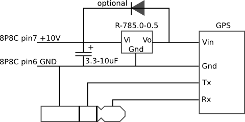
The mobile rig, a Kenwood TM-D710E, required a GPS receiver for APRS use. The GPS-710 was not readily available and was quite expensive, prompting the decision to build a custom solution. A Royaltek RGM-3600 GPS receiver was purchased on...
A collection of Kenwood TK-760G-1 transceivers (two-way radios) was programmed to a single channel, with all other features locked. Various programming software for Kenwood was gathered from the internet and local newsgroups, but a programming cable was required. The...
Electrical lines that include lighting circuits originate from the main distribution panel of the installation. Each line consists of three conductors: phase, neutral, and ground. All three conductors extend to the terminal point of each luminaire, and if the...
The Kenwood TM-733A is an older dual-band mobile radio capable of transmitting 50 watts on VHF and 35 watts on UHF. It features full-duplex crossband repeat and can simultaneously receive on two VHF or UHF frequencies. However, it is...