
Op-Amp Based PWM Circuit
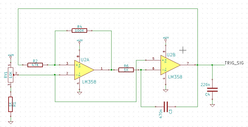
The circuit's core functionality revolves around the generation of a PWM signal, which is essential for controlling power delivery to devices such as motors or solenoids. The LM358 op-amps are configured to operate in a comparator mode, where the output signal's duty cycle can be adjusted by varying the reference voltage through the potentiometer RV1. This allows for precise control over the PWM signal, making it suitable for applications requiring variable speed or power adjustments.
The low-pass filter composed of resistor R8 and capacitor C4 plays a critical role in stabilizing the output signal. By filtering out high-frequency noise, the filter ensures that the PWM signal maintains a clean waveform, which is particularly important when driving inductive loads such as solenoids. The smoothing effect provided by this filter can prevent erratic behavior in the actuator, leading to more reliable operation.
In terms of circuit layout, careful attention should be paid to the placement of components to minimize noise and interference. The use of a single supply operational amplifier simplifies the power requirements, allowing the circuit to be powered from a straightforward DC source, which aligns with the design's goal of ease of repair and accessibility.
Overall, this circuit exemplifies a practical solution for generating PWM signals without the complexity of microcontrollers, making it ideal for applications in environments where simplicity and reliability are paramount.This circuit uses the LM358 operational amplifiers (or any single supply op amp) to generate a pulse-width modulated signal. In most cases, I would just use a microcontroller to generate PWM signals. Unfortunately, the circuit was designed for a local marine repair company which requested the circuit to be easily repairable and built without the n
eed of an external programmer, etc. Since this is rail to rail design, a reference voltage (changed using potentiometer RV1`) has to be placed on the non inverting pins of the U2A` op-amp. The R8 resistor and C4 capacitor acts as a low pass filter which will filter some a the high frequency spikes and smooth the transition peak.
I believe this portion of the circuit is optional but I just added it to make the triangle signal looks nice on my oscilloscope. Unfortunately, I have forgotten to take a picture of the completed PCB board and the working prototype.
However, I did took a picture of the 3 Amp solenoid actuator which was tested on. 🔗 External reference
Related Circuits
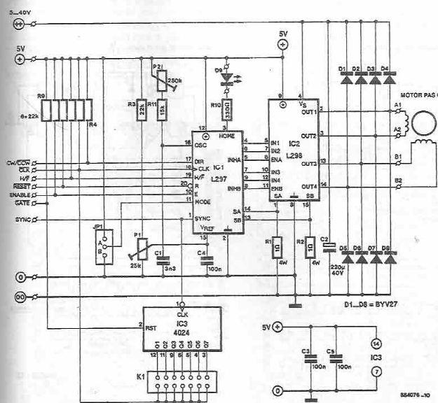
The L297 and L298 integrated circuits manufactured by SGS Thomson (ST) can be utilized to create a control circuit for a stepper motor, accommodating both two-phase bipolar and unipolar four-phase configurations, with a maximum current rating of 2 A...
The standard Class AB audio power amplifier allows for direct coupling of the amplifier's output to speakers. This is beneficial as it eliminates capacitors or transformers that could compromise sound quality. The speakers are connected directly to the amplifying...
A schematic diagram for a broadband QRP SWR metering circuit intended for use in a QRP antenna tuner. The circuit allows the user to press a momentary DPDT switch to observe an LED indicator while adjusting the capacitors of...
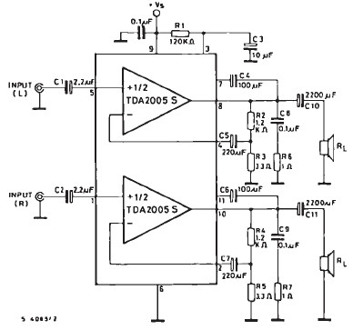
The TDA2005 car audio amplifier circuit is specifically designed for use in devices such as car radios, CD players, and similar equipment. This amplifier is based on the TDA2005 audio integrated circuit (IC), capable of delivering a maximum output...
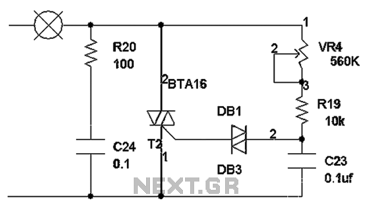
The TRIAC dimmer circuit diagram operates on the principle that a 220V lamp is controlled through the charging of capacitor C23 via resistors VR4 and R19. The charging time is influenced by the values of VR4 and R19, where...
Two-Tone Siren Circuit Schematic Using One IC. This circuit is designed for children's entertainment and can be installed on bicycles, battery-powered cars, motorcycles, as well as models and various games and toys. It includes a switch (SW1) for operation. The...