
Op-Amp-Based Wien Bridge Oscillator

The Wien bridge oscillator is a type of electronic oscillator that produces sine waves. It utilizes an operational amplifier (op-amp) in conjunction with a bridge circuit to achieve oscillation. The circuit typically consists of resistors and capacitors arranged in a specific configuration that allows for frequency stability and low distortion in the output signal.
In this design, the op-amp serves as the active component that amplifies the signal generated by the bridge network. The Wien bridge itself consists of two resistors and two capacitors, which determine the frequency of oscillation. The frequency of the output sine wave can be calculated using the formula:
\[ f = \frac{1}{2\pi R C} \]
where \( R \) is the resistance and \( C \) is the capacitance in the bridge circuit. For a target frequency of 15 Hz, appropriate values for \( R \) and \( C \) must be selected to satisfy this equation.
Additionally, the circuit may incorporate a light bulb or thermistor as a variable resistor to provide automatic gain control. This component helps to stabilize the amplitude of the oscillation, ensuring that the output remains consistent over time. As the amplitude increases, the resistance of the light bulb or thermistor changes, thereby adjusting the gain of the op-amp and maintaining a steady output level.
The output of the Wien bridge oscillator can be taken directly from the op-amp's output pin, providing a clean sine wave signal suitable for various applications, including signal processing, waveform generation, and testing of audio equipment. Proper power supply decoupling and layout considerations are essential to minimize noise and ensure stable operation of the oscillator circuit.The circuit was designed based on the functionality of an op-amp to create a Wien bridge oscillator to generate sine waves in the frequency range of 15 Hz.. 🔗 External reference
Related Circuits
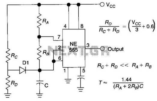
Using Rl, R7, and D1 to preset CI to one third of the supply voltage. This circuit avoids a longer first cycle period than subsequent cycles. The circuit described involves the use of resistors Rl and R7 along with diode...
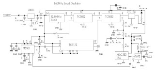
This 860 MHz Phase Locked Loop (PLL) oscillator circuit is designed for a 1200 MHz transverter's local oscillator with 435 MHz rigs. The oscillator utilizes Toshiba PLL synthesizer integrated circuits (ICs). The TC9122P serves as a preset counter for...
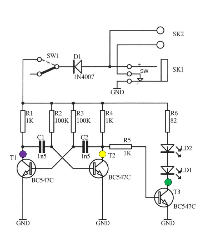
The schematic circuit presented below illustrates an infrared transmitter. The infrared beam is emitted in a nearly line-of-sight manner towards another device equipped with an infrared receiver. The displayed waveforms represent the output voltages from two intermediate stages (purple...
An oscillator is a circuit that generates a frequency source such as a sine wave, square wave, or pulse train. It combines a frequency-sensitive circuit, like an LC circuit or a crystal, with a negative resistance typically provided by...
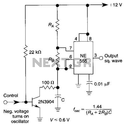
This gated 1-kHz oscillator provides a press-to-turn-on functionality, with waveforms available at the output of pin 3 and across capacitor CI. The gated 1-kHz oscillator circuit is designed to produce a square wave output that can be activated by a...
A very popular circuit for driving DC motors (ordinary or gearhead) is called an H-bridge. It's called that because it looks like the capital letter 'H' on classic schematics. The great ability of an H-bridge circuit is that the...