
op amp lm741 pre amp mic schematic

The Op-Amp Microphone Preamplifier circuit is designed to amplify low-level audio signals from microphones, making it suitable for various audio applications, including recording and live sound reinforcement. The circuit employs a single power supply, simplifying the design and making it more versatile for portable applications.
In the non-inverting configuration, the op-amp amplifies the input signal without inverting its phase. The input signal from the microphone is fed into the non-inverting terminal of the op-amp, allowing for high input impedance, which is crucial for interfacing with microphones that typically have high output impedance. The input impedance of 23.5 kΩ ensures minimal loading on the microphone, preserving the integrity of the audio signal.
For dynamic microphones, the schematic directly connects the microphone output to the non-inverting input of the op-amp. In contrast, electret microphones require additional biasing to operate correctly. This is achieved by connecting a pair of resistors to the power supply, which provides the necessary voltage for the electret microphone while also allowing the audio signal to pass through to the op-amp.
The gain of the amplifier is set by the feedback network formed by resistors R1 and R2. The voltage gain (Av) can be calculated using the formula:
Av = 1 + (R2 / R1)
This formula indicates that the gain is determined by the ratio of the resistors, allowing for easy adjustment according to the desired amplification level. Selecting appropriate values for R1 and R2 is critical for optimizing the performance of the preamplifier and ensuring that the output signal is strong enough for further processing or amplification stages.
Overall, this Op-Amp Microphone Preamplifier circuit is an effective solution for amplifying audio signals with flexibility for different microphone types, making it a valuable component in audio signal processing systems.This is the circuit of Op-Amp Microphone Preamplifier using a single power supply, this circuit suitable for dynamic or electret microphones. Nothing too special here. The Schematic is shown using a dynamic microphone, for use with an electret a pair of suitable biasing resistor is required to power the electret microphone.
The design is a standar d non-inverting design, the input is applied to the non-inverting input of the op-amp, which is pin 3 in most cases. The input impedance is 23. 5k, the overall voltage gain is determined by R2 and R1according to the following formula: 🔗 External reference
Related Circuits
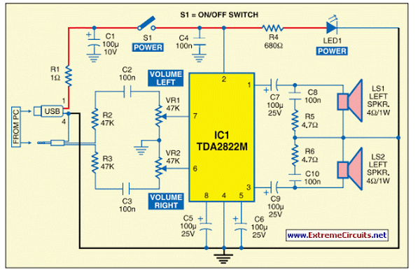
This circuit of multimedia speakers for PCs features a single-chip design, operates on a low-voltage power supply, is compatible with USB power, and allows for easy heat dissipation. The multimedia speaker circuit is designed to enhance audio output for personal...
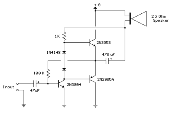
This circuit is similar to the previous one but employs positive feedback to enhance the amplitude delivered to the speaker. It was derived from a small 5-transistor radio utilizing a 25-ohm speaker. In the previous circuit, the load resistor...
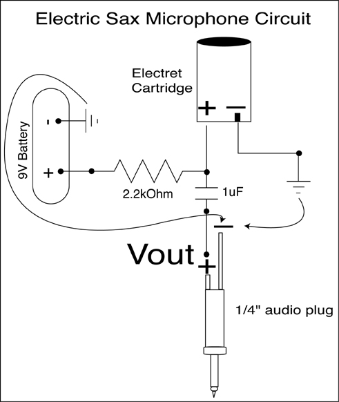
A condenser microphone (electret type with two terminals) is to be powered. A resistor of 1 kΩ and a capacitor of 10 µF have been connected to its positive terminal, while the other terminal is grounded. To power an electret...
This circuit turns off an amplifier or any other device when a low-level audio signal fed to its input is absent for 15 minutes at least. Pushing P1, the device is switched on, feeding any appliance connected to SK1....
Very simple, versatile modular design. The purpose of this circuit was to create a ring in which LEDs or Lamps illuminate sequentially. Its main feature is a high versatility: you can build a loop containing any number of LEDs...
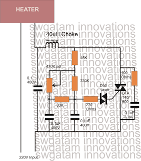
Controlling heaters rated up to 1500 watts requires stringent specifications for the controlling unit to ensure safe and effective operation. The introduction of advanced snubber-less Triacs and Diacs has made it relatively easier to implement heater controllers at high...