
OP90 4 mA to 20 mA Current Loop Transmitter
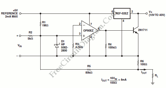
The current transmitter operates within a specified range, providing an output current that is directly proportional to the input voltage. This is typically used in industrial applications for process control, where it translates varying voltage levels into a standardized current signal for further processing or monitoring.
The output range of 4 mA to 20 mA is a common standard in industrial automation, allowing for easy integration with various control systems and devices. The lower limit of 4 mA usually indicates a zero input voltage, while the upper limit of 20 mA corresponds to the maximum input voltage. This linear relationship ensures that any changes in the input voltage result in a corresponding change in the output current, which can be easily measured and interpreted by downstream devices.
Line rejection refers to the ability of the current transmitter to filter out noise and interference from the power supply or other external sources. This ensures that the output signal remains stable and accurate, even in environments with fluctuating electrical conditions. Effective line rejection is crucial for maintaining the integrity of the signal, particularly in applications where precision is essential.
The schematic of the current transmitter would typically include components such as operational amplifiers, resistors, and capacitors configured to achieve the desired gain and linearity. The input stage may include a differential amplifier to accurately measure the input voltage, while the output stage would be designed to convert this voltage into the specified current output, often utilizing a transistor or a current loop driver.
Overall, this current transmitter is an essential component in many electronic systems, providing reliable and accurate signal conversion for various applications.An output of 4 mA to 20 mA that is linearly proportional to the input voltage is provided by the current transmitter on figure below. Line rejection is. 🔗 External reference
Related Circuits
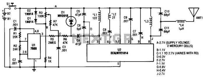
This transmitter can be utilized for multiple applications. An INS8048L microprocessor produces various codes based on keypad inputs. These codes are modulated onto a 40-kHz carrier frequency. Additionally, Q1 drives infrared LEDs LED1 and LED2. The transmitter circuit primarily consists...
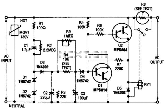
Q1 is an NPN Darlington transistor, and Q2 is a PNP Darlington transistor. MOV1 is a metal-oxide varistor, while R8 is a thermistor used for limiting inrush current. This circuit is designed to limit AC line current to a...
This circuit generates audio musical notes that can be heard from a distance of up to 10 meters. The circuit is divided into two parts: an infrared (IR) music transmitter and a receiver. The circuit operates on the principle of...
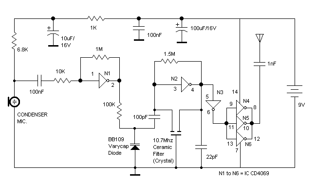
The RF oscillator using the inverter N2 and 10.7MHz ceramic filter is driving the parallel combination of N4 to N6 through N3. Since these inverters are in parallel, the output impedance will be low so that it can directly...
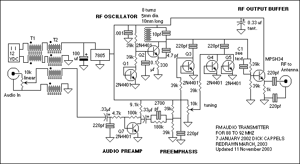
The circuit consists of a frequency modulated oscillator, an audio preamplifier with pre-emphasis to supply the frequency modulating signal, and a buffer amplifier to drive the antenna connector. Oscillator's frequency is determined by L1 resonating with the 10 pF...
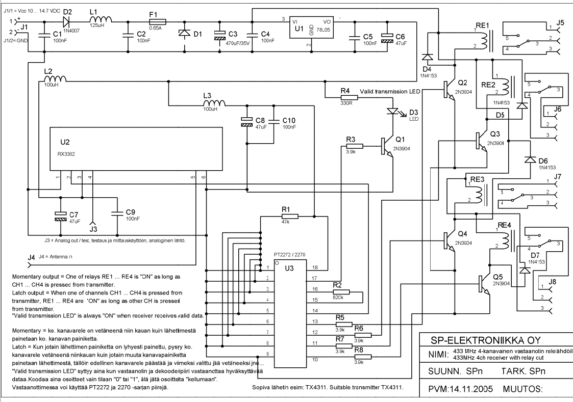
Momentary output: One of the relays RE1...RE4 is ON as long as CH1---CH4 is pressed from transmitter. Latch output: when one of channels CH1...CH4 is pressed from transmitter RE1...RE4 are ON as long as other CH is pressed from...