
Opamp Design and Test Board
The project described involves the use of a medium-sized un-etched printed circuit board (PCB) as a prototyping platform. This approach allows for flexibility in circuit design and experimentation, making it suitable for rapid development and testing of electronic concepts. The un-etched PCB serves as a versatile base where components can be placed and connected without the need for a pre-defined circuit layout.
To create the prototype, the following components may be utilized: resistors, capacitors, integrated circuits (ICs), transistors, and connectors, depending on the specific application being tested. The layout on the PCB can be customized according to the circuit requirements, allowing for modifications and adjustments as ideas evolve.
The un-etched PCB can be easily cut to size, accommodating various project scales. It is advisable to use a soldering iron for attaching components securely to the board, ensuring reliable electrical connections. Additionally, jumper wires can be employed for connecting different parts of the circuit, facilitating easy alterations during the prototyping phase.
For power supply, a standard voltage source may be utilized, ensuring it matches the requirements of the components used. The prototyping process may also involve the use of a breadboard for initial testing before finalizing the design on the PCB.
Overall, this prototyping method is cost-effective and provides a practical approach for developing and refining electronic ideas, making it an ideal choice for hobbyists and engineers alike.This project is basically what I use for a quick prototype, or for just mucking about with an idea. It is easy to make, and only needs a medium size sheet of un-etched printed circuit board (or possibly two). This can usually be obtained from electronics suppliers, and is not overly expensive. 🔗 External reference
Related Circuits
The sphygmomanometer can be categorized into two main types: the mercury sphygmomanometer and the electronic sphygmomanometer. The mercury sphygmomanometer is known for its accuracy, but it requires professional operation and is prone to observational errors due to subjectivity. Additionally,...
This design will appeal to technicians working with pneumatically operated valves and other devices controlled by a 4-20mA current loop. While 4-20mA signal injectors and calibrators are available, this particular model is cost-effective to construct and user-friendly. Upon initial...
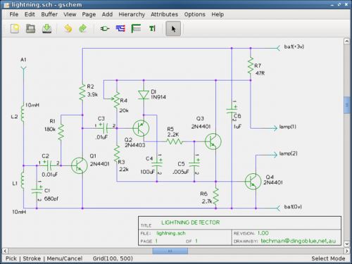
Are you looking for a free schematic and PCB design tool? The gEDA project has produced and continues to work on a complete GPL licensed suite and toolkit for electronic design. The gEDA project offers a comprehensive suite of tools...
The design of a current difference buffer amplifier (CDBA) circuit for fabrication in a commercial CMOS semiconductor process allows for the versatile application of this component across various uses. The current difference buffer amplifier (CDBA) is a specialized analog circuit...
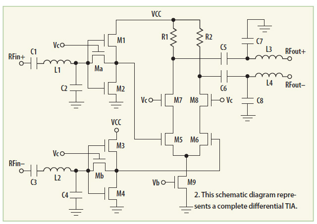
This module utilizes the highly integrated MAX2830 RF transceiver, providing a complete RF front-end solution that complies with the WLAN IEEE 802.11b/g standard. The MAX2830 RF transceiver is designed for wireless communication applications, specifically targeting WLAN systems. It integrates various...
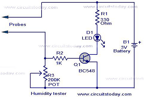
A simple humidity tester circuit using only an LED, a transistor, and a few resistors is explained with a clear circuit schematic. The humidity tester circuit is designed to provide a visual indication of humidity levels using basic electronic components....