
Open Decoder Schematics
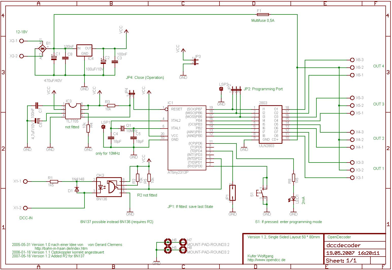
The circuit design incorporates multiple features that enhance functionality and reliability in model railway applications. The use of the ATtiny2313 microcontroller allows for compact integration with minimal external components. The power supply management, including rectification and voltage regulation, ensures stable operation of the processor and connected devices. The inclusion of opto-couplers provides electrical isolation, safeguarding the microcontroller from voltage spikes and fluctuations in the DCC signal.
The ULN2803 output driver is essential for controlling inductive loads such as turnout drives, providing adequate current handling and protection against back EMF. The design's modular approach, allowing for optional components, enables flexibility in implementation based on specific operational requirements. Furthermore, the attention to detail regarding component selection and configuration ensures that the system operates efficiently in various scenarios, making it suitable for both hobbyist and professional model railway setups. Overall, this schematic represents a well-thought-out solution for controlling model railway turnout drives, balancing performance, reliability, and ease of use.This software was written for this hardware. Therefore the pin allocation of the Atmel Attiny2313 in this curciut corresponds to the orginal of So the software will run on both hardware platforms. Important note: The processor AT90S2313 requires an external reset generator (TL7705) as well as an external quartz.
With the processor ATtiny2313 these parts aren`t needed (but you will find them in the diagram as an option). If the quartz is omitted, the Attiny must be set for 8MHz and internal oscillator and the source must be compiled for 8MHz as well. So with the ATtiny2313 you can leave out: C4, C5, C6, C7, R3, R4, IC3 and Q1. At X2 the input voltage of the external power pack is fed in (approx. 15V); Polarity and type of current doesn`t matter: a transformer for model railways, a plug power pack or the DCC signal itself can be used.
The input voltage is rectified and by means of the usual 7805 limited to 5V for the supply of the processor. The idle current amounts to approx. 20mA. Note: I stated that some magnetic turnout drives from Roco need up to 15V to operate properly; In this case supply voltage is to be increased by the voltage drops at the rectifiers and output drivers to 16V~ or 18V=.
To X1 the DCC signal is attached. This is separated by means of an opto coupler from the voltage supply of the decoder. The opto coupler provides a troublefree operation even on large layouts. Usable as opto coupler is 6N136 or 6N137 or even 4N25. When using the 6N137 the pin 7 (enable) must be connected to pin 8 (this is not in the layout of the pcbs V1. 1). The 4N25 (or its derivatives) must be equipped in such a way, that pin 1 of the 4N25 coresponds to pin 2 of the layout.
The 4N25 is slow, in particular the recovery time is relatively long. Therefore the pullup at the output should be changed to 1k. This is done by means of ULN2803: this chip can supply 0. 5A at each output and is internally equipped with a flywheeling diode for inductive loads. This is sufficient for N gauge, with H0 0. 5A may be to less. Some drives may require more current. The outputs are arranged in groups of two with a power supply in the middle. Thus the wiring of the layout is made easier, no need for extra connectors to distribute power. Turnout drives are typically equipped with coils, these are automatically turned off at the end of the travel. This turning off causes an induction voltage, which flows backwards to the output driver and is captured by the integrated flywheeling diode.
If the switch for turning off is `ringing` and turns off and on several times, then it can happen that the flywheeling diode is overloaded before the polyfuse switches off. This can be done either by means of a a bistabile relay or with a transistor stage. Christian Wichmann created a pcb layout for a decoder with these outputs. Atmel ATtiny2313 is used as processor. There is an optional reset generator chip (TL7705) in the layout of the pcb. This was necessary with the predecessor AT90S2313, in order to avoid brownout. This is no longer needed, since the the Attiny2313 has a built in reset generator. The Atmel ATtiny2313 is delivered with a factory adjusted RC oscillator, which runs at 8 MHz. Therefore the quartz and the condensers can be omitted. However then a hex file for 8 MHz must be loaded. When doing the compilation with a set clock rate (F_CPU) of 8000000, all timing setups are adjusted automatically.
HEX files for both 10MHz and 8MHz are contained in the zip file below. Note: the clock accuracy is indicated by Atmel as 10%, what is sufficiently exact for this application; however, in a worst case scenario (combining clock deviation, delay time of optocoupler and a DCC input at tolerance edge) the reception of DCC may fail. So consider using a quart 🔗 External reference
Related Circuits
This circuit should only be attempted by individuals with a strong understanding of electronic devices. It is connected to a main power source (220V) and poses a risk of high electrical shock. This circuit operates at a mains voltage of...
The TDA2005 integrated circuit (IC) features a high output power of 10W per channel (stereo) at a load of 2 ohms with a distortion of 10%, and 20W in bridge mode at a load of 4 ohms with a...
This circuit utilizes the TLC555CP timer integrated circuit to flash an LED approximately twice per second. This specific 555 timer operates on a voltage of only 3 volts, allowing it to be powered by two 1.5-volt cells. When using...
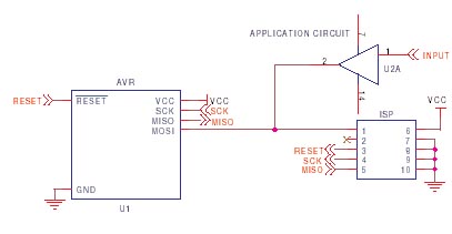
It is crucial to design the PCB layout correctly to enable seamless In-System Programming (ISP) of AVR microcontrollers. This guide addresses common issues encountered and provides typical AVR ISP circuit schematics. It focuses on Serial Programming, known as ISP,...
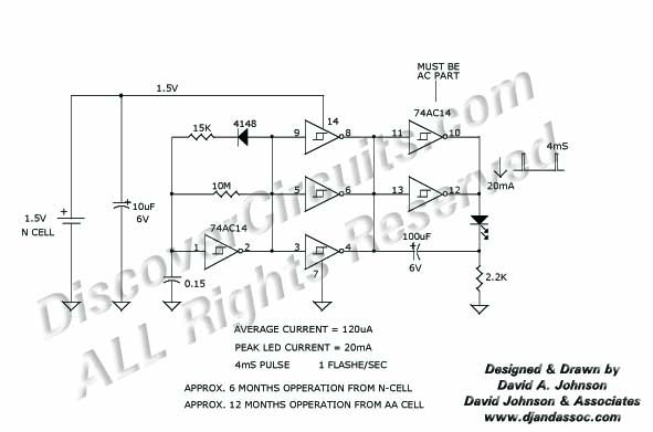
Many published circuits that flash LEDs require 3 volts or more. This circuit utilizes a single inexpensive C-MOS IC and can flash an LED for an entire year on a single 1.5-volt AA alkaline battery cell. The circuit employs...
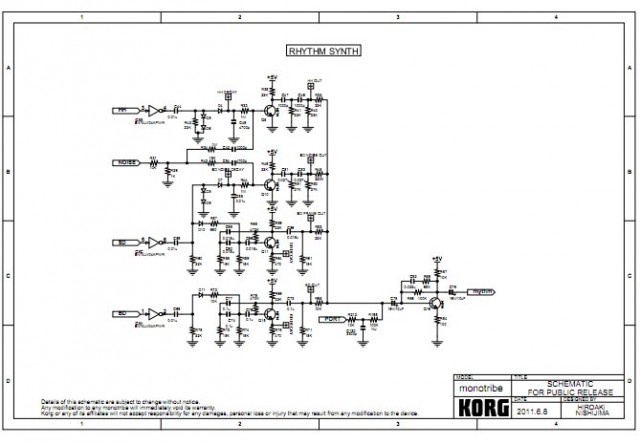
Korg has released schematics for the analog drum synthesis section of its Monotribe synthesizer and step-sequencing rhythm machine. The schematics focus on the components responsible for generating drum sounds, which are the most interesting and modifiable aspects of the...
Warning: include(partials/cookie-banner.php): Failed to open stream: Permission denied in /var/www/html/nextgr/view-circuit.php on line 713
Warning: include(): Failed opening 'partials/cookie-banner.php' for inclusion (include_path='.:/usr/share/php') in /var/www/html/nextgr/view-circuit.php on line 713