
Optical Direction Discriminator Circuit
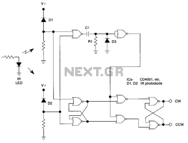
The described circuit leverages the CD4001 NOR gate IC to create a simple yet effective rotational direction detector. The RS flip-flop serves as a memory element that retains the state corresponding to the direction of rotation, which is determined by the input pulse frequency and duty cycle. The integration of R1, C1, and D3 in conjunction with the NOR gate inverter is crucial for generating short pulses that are essential for accurate sampling of the flip-flop outputs.
In this arrangement, the first RS flip-flop captures the state of the incoming pulse stream, while the second RS flip-flop is used to provide a stable output indicating the direction of rotation. When the input pulses exhibit a high duty cycle, the resultant output from the first flip-flop leads to a consistent pulse train from the sampling NOR gate. This pulse train is instrumental in toggling the second RS flip-flop, ensuring that the output remains in a state that reflects the current rotational direction.
The circuit's design is particularly advantageous for applications requiring real-time monitoring of rotational motion, such as in motor control systems or rotary encoders. The use of standard logic components like the CD4001 allows for straightforward implementation and integration into larger systems. The simplicity of the design, combined with the reliability of the NOR gate logic, makes this circuit an ideal choice for detecting and indicating the direction of rotation in various electronic applications. The very simple circuit uses only two CD4001 packages, i.e., eight NOR gates and operates in the following way: Pulse streams are fed to an RS flip flop generating an output waveform wliich has a small or large duty cycle depending on the direction of rotation, The same input pulses are also fed to a NOR gate, which adds the two pulse trains. The rising edges of this waveform are used to produce short positive pulses from the circuit consisting of Rl, CI, D3, and a NOR gate used as an inverter.
This is used to sample the outputs of the flip flop to detect the direction of rotation. The output, whose duty cycle is large, forces the sampling NOR gate to generate a pulse train which sets (or resets) the second RS flip-flop continuously giving a permanent indication of the direction of rotation. 🔗 External reference
Related Circuits
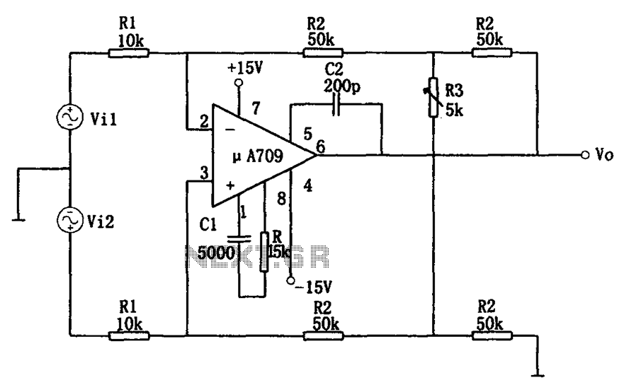
The configuration of the variable gain A709 differential amplifier circuit is illustrated. The primary advantage of this circuit is its ability to maintain a constant common-mode rejection ratio (CMRR) while allowing for continuous adjustments to the differential gain. The...
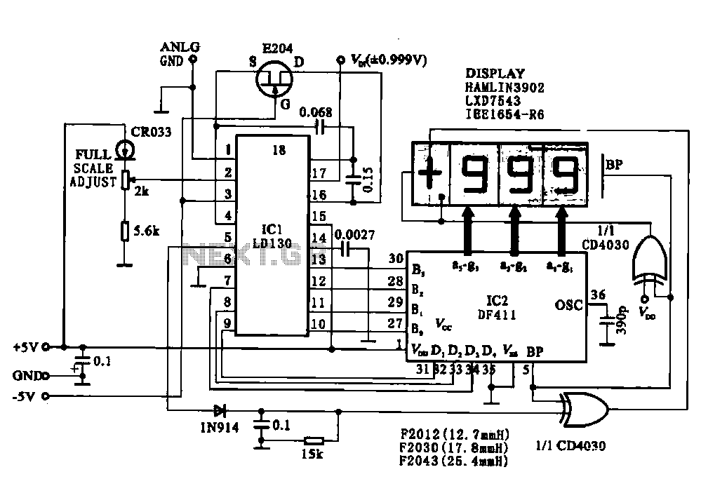
This circuit illustrates a display driving system for a digital voltmeter. The liquid crystal display (LCD) does not emit light by itself; it relies on external incident light for visibility. The integrated circuit (IC) LD130 serves as an input...
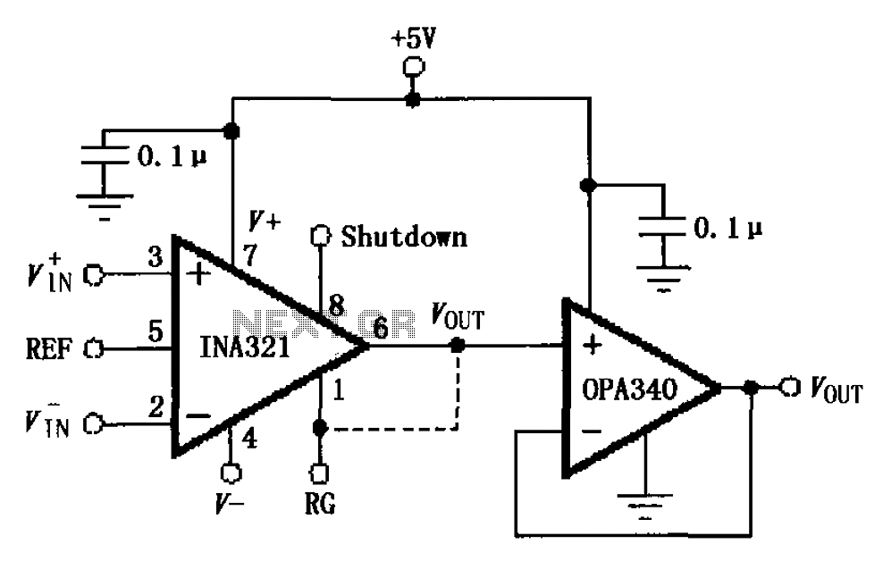
The circuit depicted in the figure consists of an OPA340 operational amplifier configured as a voltage follower, serving as an output buffer for the INA321/322 output. The optimal load impedance for the INA321/322 is 10k ohms or greater. A...
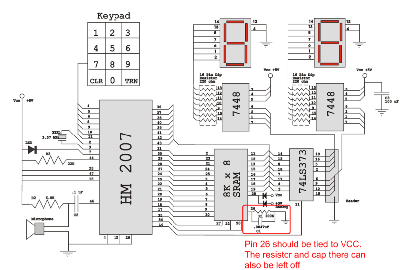
Verify the pin configurations on the datasheets for the integrated circuits used in your project, making necessary adjustments. In this instance, the RAM chip utilized had a non-inverted enable signal on pin 26, while the schematic assumed it was...
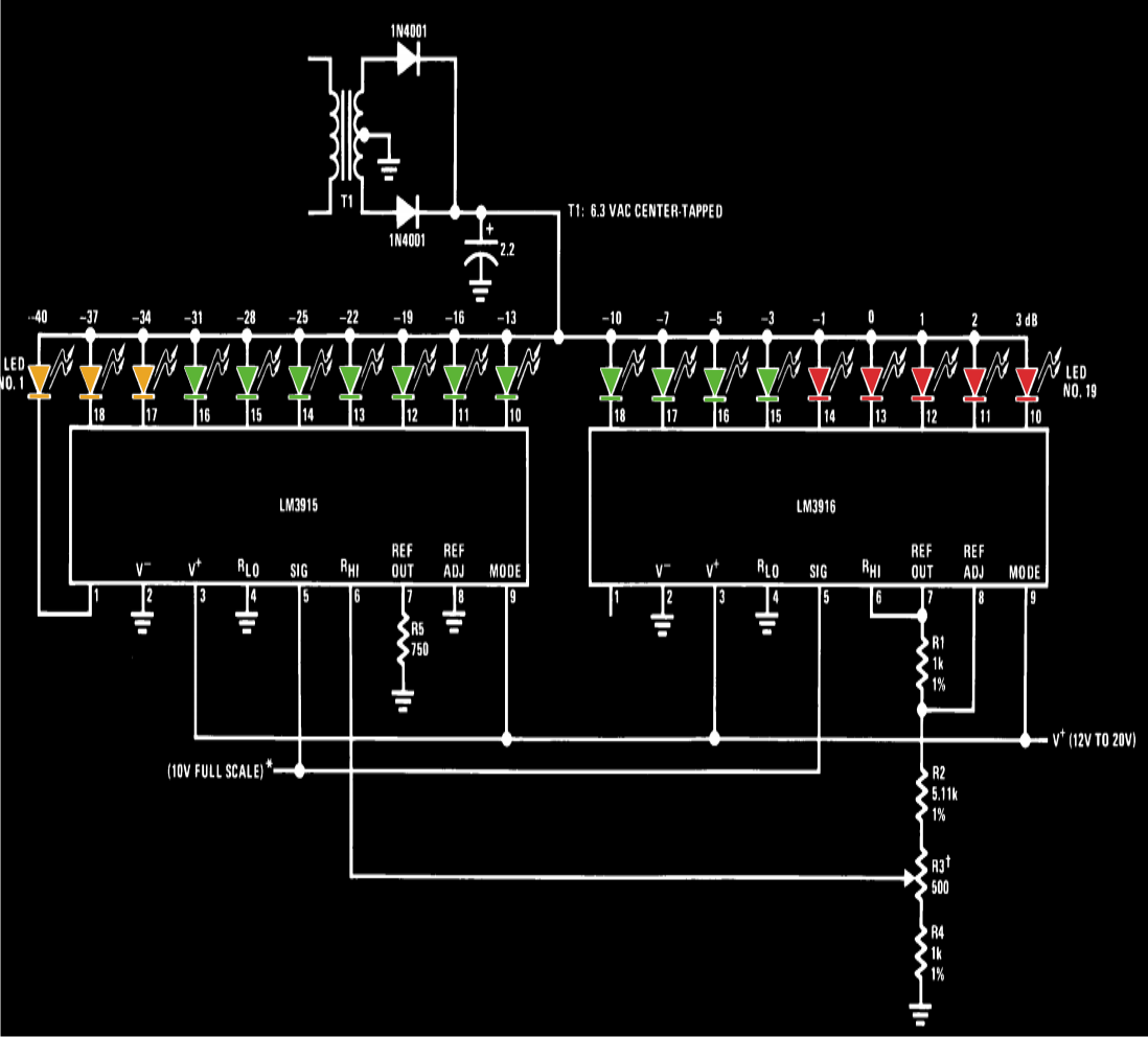
A VU meter, or volume unit meter, is a device used to indicate the music volume output from an amplifier or loudspeaker system. It can also be viewed as a device for displaying the PMPO (Peak Music Power Output)...
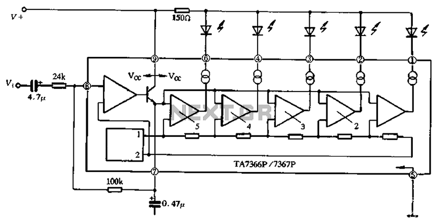
The TA 7366/7367 is a commonly used single display driver circuit manufactured by Toshiba Corporation. It features a 5 LED driver circuit and is designed in a 9-pin single in-line plastic structure. The circuit configuration includes an operational amplifier...
Warning: include(partials/cookie-banner.php): Failed to open stream: Permission denied in /var/www/html/nextgr/view-circuit.php on line 713
Warning: include(): Failed opening 'partials/cookie-banner.php' for inclusion (include_path='.:/usr/share/php') in /var/www/html/nextgr/view-circuit.php on line 713