
how to make simple vu meter circuit at
The VU meter circuit serves as an effective tool for visualizing audio levels, enhancing the aesthetic appeal of audio equipment while providing functional feedback about the output levels. The use of two integrated circuits in a cascaded configuration allows for a more refined control over the LED sequencing, offering a smoother transition between levels as the music's amplitude changes. The choice of a 20 LED bar graph provides a clear visual representation of volume levels, allowing users to easily gauge the output at a glance.
In terms of implementation, the circuit can be powered by the existing amplifier supply, which simplifies the overall design and reduces the need for additional components. This integration not only minimizes the physical footprint of the setup but also enhances reliability by reducing the number of separate power sources.
The adjustment resistor R3 plays a critical role in tailoring the responsiveness of the LEDs to the audio signal, allowing users to customize the display to their preferences. By manipulating this resistor, the sensitivity of the VU meter can be fine-tuned, ensuring that the visual output corresponds accurately to the audio input levels.
For housing, while an external enclosure is suggested, integrating the VU meter into the amplifier's dashboard may provide a more cohesive look and feel to the overall setup. This integration requires careful planning regarding the layout and the drilling of mounting points to ensure that the installation is both functional and aesthetically pleasing.
Overall, the VU meter circuit not only serves a practical purpose but also enhances the user experience by providing a visually engaging representation of audio levels, making it a valuable addition to any audio system.VU meter or a volume unit meter is a device used for indicating the music volume output from an amplifier or a loudspeaker system. It may be also considered as a device for displaying the PMPO of the amplifier at a particular volume setting.
Though the unit looks quite technical, which is applied as a measuring device of audio power, in real terms these are more like decorative ornaments of an amplifier. Without such devices attached, an amplifiersystemwould lookquitedull and without any juice. Prior to the days when LEDs were not so popular, moving coil meter type ofdisplayswere commonly incorporated as VU meters and surely these units with there back lights ON produced a distinctive visual effect as their needles deflected from left to rightdisplayingthe varying pitch of the connected audio system. With color effect at its disposal, LEDs became the HOT favorites as far as VU meter were concerned, even todayamplifiers employ a LED VU graph fordisplayingthe music power in an amplifier.
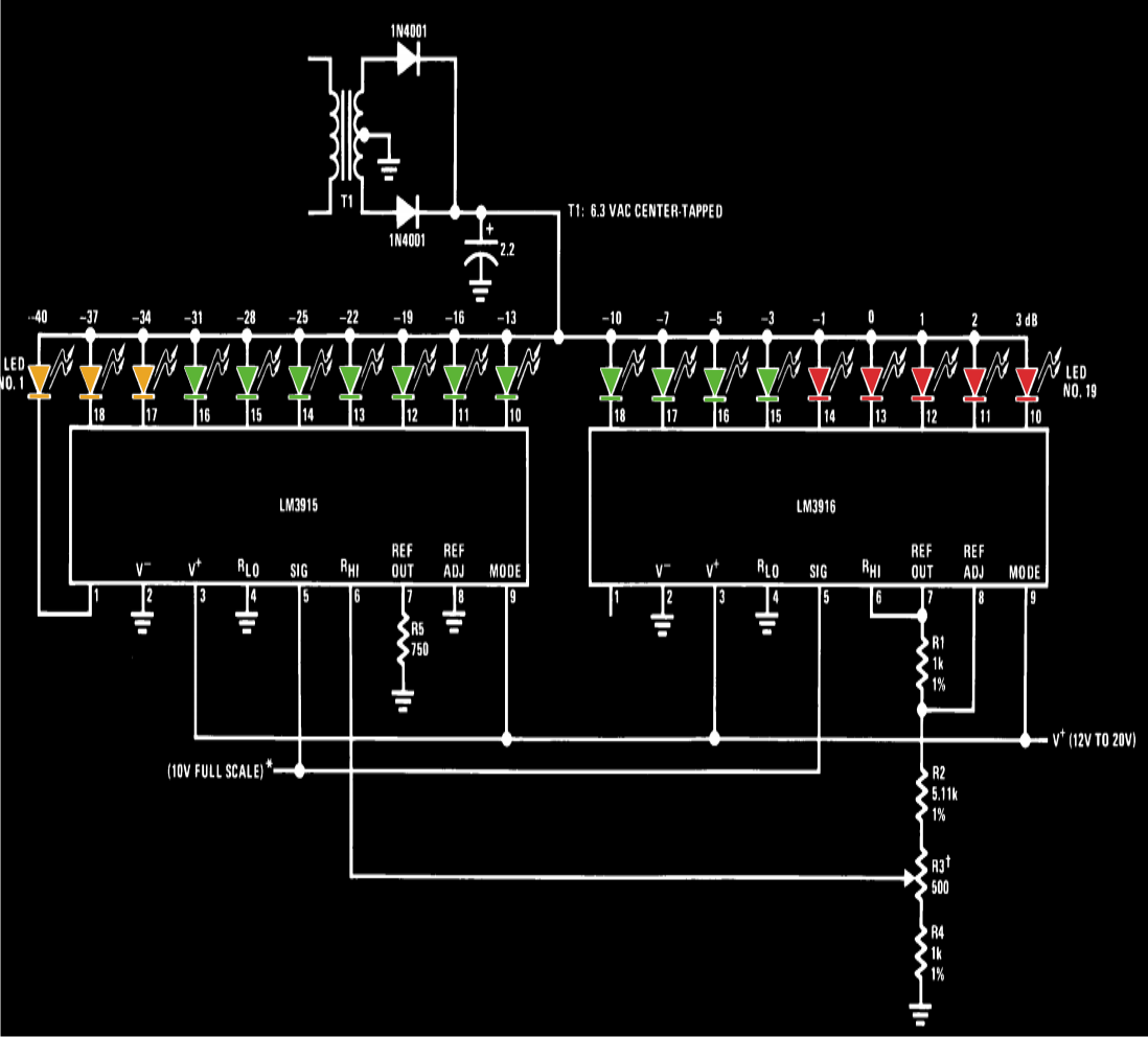
For electronic hobbyists who are rather more interested in building a particular required gagdet right at home instead of buying a commercial piece, this cool VU meter circuit will interest them if they are intending to make one for their musicsystem. The circuit diagram shows a very simple configuration employing two of the above ICs in the cascaded form forproducinga good 20 LED sequencing bar type indication.
R3 has been stationed for adjusting thetypicaldB levels between the LEDs forenablingvisually more enhancedsequencingpattern in response to the fed music input. The diagram shows a separate power supply being used for the circuit, however if the amplifier supports a 12 volt stabilized power supply, can beused forpowering the circuit as well, this would help to get rid of the extra bulk involvingthetransformer and the associated rectificationcircuitry.
An external enclosure may be used for housing theassembledcircuit or possibly thecircuitmay be installed in the amplifier dashboard itself, if situation permits the requireddrillingandfittings. 🔗 External reference
Related Circuits
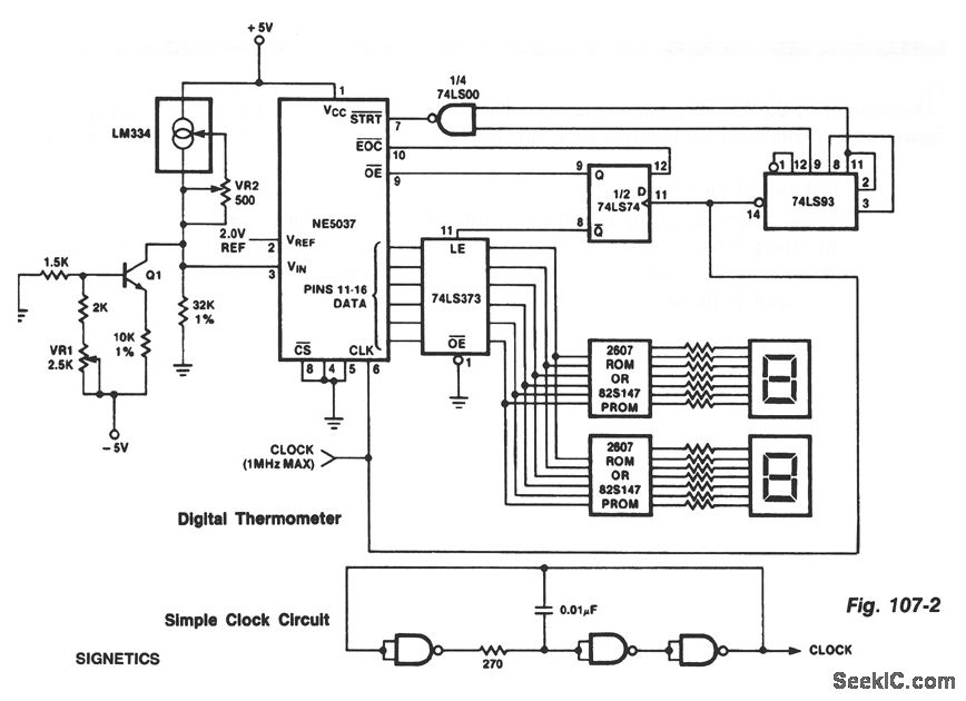
The ROMs or PROMs must contain the correct code for converting data from the NE5037, which serves as the address for the ROMs or PROMs, into the appropriate segment driver codes. The displayed temperature can be converted to degrees...
This is a circuit diagram of a simple circuit in which the LED can be activated only by a gust of air. A condenser microphone (M1) is used to detect breath. When the S1 button is pressed, transistors Q2...
This project involves an automatic street light or lamp circuit designed to activate outdoor lights, such as garden lamps and night lights, automatically at sunset and turn them off at sunrise. The circuit is sensitive and versatile, capable of...
Here is a simple circuit which can be used for decoration purposes or as an indicator. Flashing or dancing speed of LEDs can be adjusted and various dancing patterns of lights can be formed. The circuit consists of two...
Unfortunately, there is no breadboard available for testing; however, modifications can be made to the PCB. The 1K potentiometer has been removed until the strobe functionality can be established. The circuit in question appears to involve a strobe light mechanism,...

U2-a, U3, and R2 function as an integrator. Q2 and Q3 are alternately switched at 256 cycles. U2-b, Q4, Q5, and R8 through R11 form a constant current generator, with R11 configured to produce a symmetrical triangular waveform. The circuit...