
Optical schmitt trigger
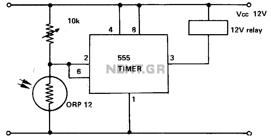
The described circuit employs a 555 timer in monostable mode, where the trigger and threshold inputs are tied together to create a single point of control. The photoconductive cell, or LDR (Light Dependent Resistor), acts as a light sensor, varying its resistance based on the ambient light levels. When the light intensity decreases below a specific level, the resistance of the LDR increases, causing a voltage drop across it that triggers the 555 timer.
In this configuration, the output of the 555 timer is connected to a relay, which allows the circuit to control higher power loads or devices. The relay serves as an electromechanical switch that can be activated by the low output current from the 555 timer. This is particularly useful in scenarios where it is necessary to control lights, alarms, or other devices based on light conditions.
The circuit's design ensures high input impedance, which is advantageous for interfacing with the LDR, as it minimizes the loading effect on the sensor. The low output impedance of the 555 timer ensures that it can drive the relay effectively without additional buffering components, thereby simplifying the overall design and reducing the component count.
This circuit can be adapted for various applications, such as automatic lighting systems, security alarms, or any system that requires light level monitoring and control. The minimal component count not only reduces costs but also enhances reliability and ease of assembly, making it an attractive solution for both hobbyists and professionals in the field of electronics.This circuit shows a 555 with its trigger and threshold inputs connected together used to energize a relay when the light level on a photoconductive cell falls below a preset value Circuit can be used in other applications where a high input impedance and low output impedance are required with the minimum component count. 🔗 External reference
Related Circuits
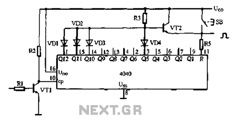
An analog electronic clock that utilizes a trigger signal for operation. An analog electronic clock typically employs a trigger signal to manage its timekeeping functions. The clock's primary components include a quartz crystal oscillator, which provides a stable frequency reference,...
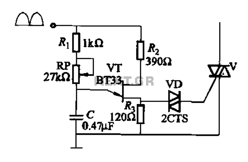
Figure 16-29 (a) illustrates the trigger output through a resistor R2, while Figure 16-29 (b) depicts the integration of a programmable unidirectional transistor (PUT) trigger circuit. The adjustable potentiometer RP can modify the conduction angle of the TRIAC to...
A Theremin typically operates by detecting hand proximity through the capacitive coupling method. The Theremin circuit illustrated in the schematic diagram below employs a different technique to control pitch. In this optical Theremin, the oscillator of the tone generator...

This circuit features a 100 mV hysteresis, suitable for applications that demand rapid transition times at the output, even when the input signal is relatively slow. Additionally, the hysteresis loop minimizes false triggering caused by noise in the input. The...
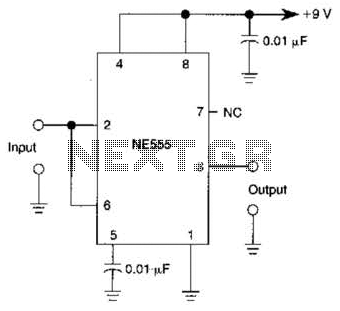
A 555 IC is configured to function as a Schmitt trigger. Inputs above and below the threshold level will turn the circuit on and off, producing a square wave output. The 555 timer integrated circuit (IC) is a versatile device...
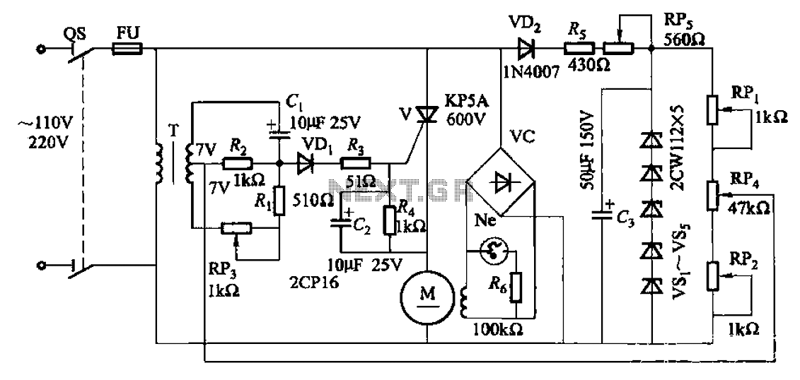
A 35W resistive and capacitive half-wave phase-shift trigger control circuit is designed for automatic or semi-automatic welding equipment to manage wire feeding and welding carriage travel. This system necessitates a drive control circuit to fulfill the welding process requirements....