
Theremin with ZapperlaserArduino

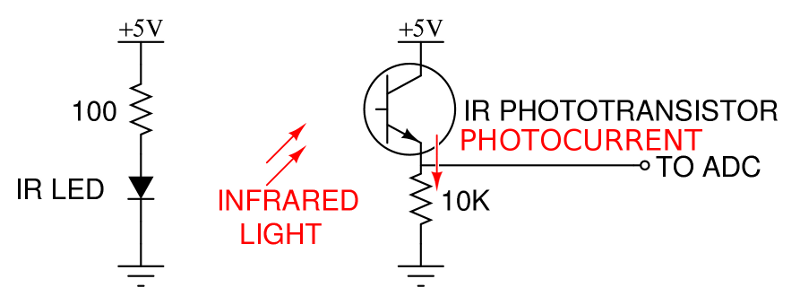
The schematic design based on the described parts list involves a laser harp assembly that integrates six laser emitters. Each laser is typically paired with a photodetector that senses interruptions in the laser beam, allowing for the generation of sound or control signals when the beam is broken.
The circuit may include a microcontroller to process the signals from the photodetectors, enabling the translation of physical interaction into audio output. The microcontroller can be programmed to assign different tones or functions to each laser beam, enhancing the musical capabilities of the harp.
Power supply considerations are essential; the circuit should include voltage regulators to ensure that each component receives the appropriate voltage levels. Additionally, resistors may be used in series with the lasers to limit current and prevent damage.
The layout of the circuit board should facilitate easy access to all components for maintenance and modifications. Proper grounding techniques must be employed to minimize noise and ensure stable operation.
In summary, the design focuses on a straightforward implementation of a laser harp with a simplified parts list, emphasizing the integration of laser emitters, photodetectors, and a microcontroller to create an interactive musical instrument.Basically I used the parts list that is on the first page of the Make Magazine article. But that list is for the harp which has 6 lasers so most quantites can be just 1. 🔗 External reference
Related Circuits
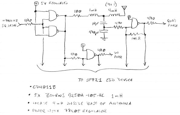
The circuit mentioned is significantly less effective than Lev's Oscillator for Theremin applications. The simulation waveforms indicate the red sine wave represents the voltage on L1:A, the black sine wave indicates the voltage on Q1:D, and the blue square...
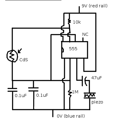
A theremin is an instrument that can be played by changing the proximity of hands to its sensors. Traditional theremins produce classic spacey and eerie sounds commonly associated with sci-fi and horror films. The version discussed here is a...
Two identical integrated circuits, U1 and U2, known as "hex inverters," are utilized for the primary functions of the theremin. These are CMOS (Complementary Symmetry Metal Oxide Semiconductor) devices commonly employed in digital circuits to perform a logic function...
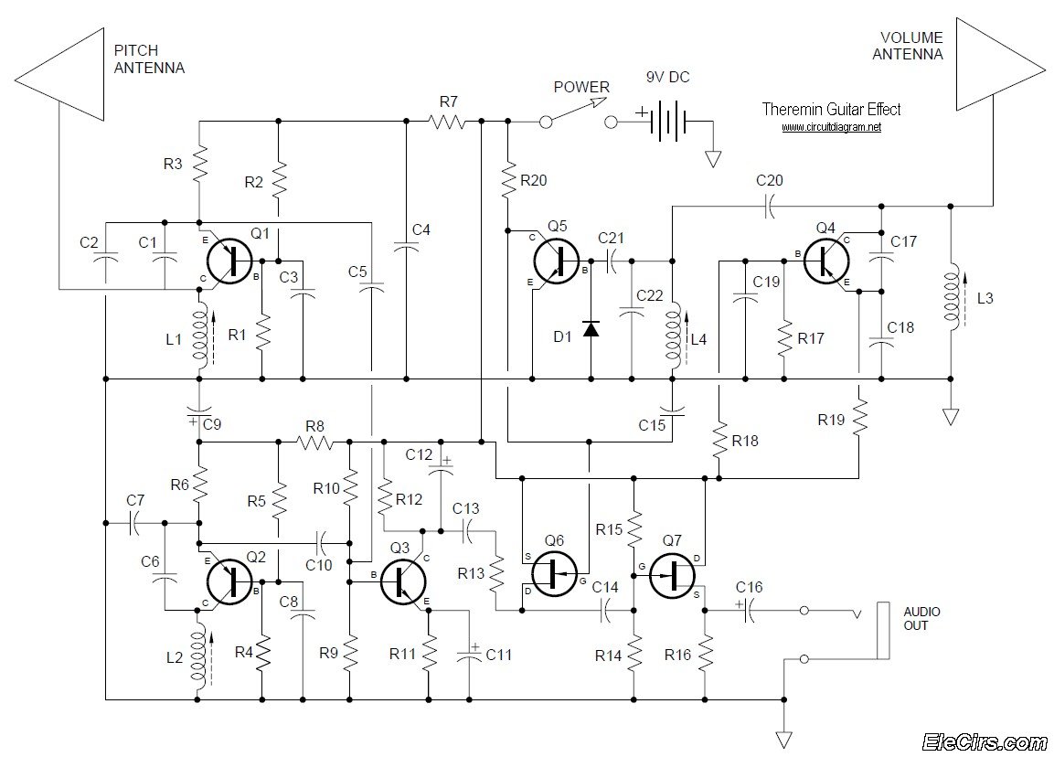
Below is the circuit diagram for the Theremin music instrument effect. A guitar or instrument amplifier is an ideal companion for the Theremin, allowing for bass or treble boost as desired, as well as fuzz (distortion) or reverberation if...
Halloween is an opportunity to showcase innovative homemade electronics. In this Halloween video tutorial, a theremin-inspired musical instrument has been integrated into a costume. This design allows the wearer to have a costume that is loud and engaging for...
Adrian Bontenbal has provided updated notes from his experiments in recreating Clara Rockmore's theremin. Bob Moog shared his hand-drawn schematic for Clara's instrument over a decade ago. Adrian started with that schematic to build his own Rockmore theremin. During...