
Optically isolated RS485 circuit diagram of a typical

The RS485 bus circuit is designed to facilitate robust communication in environments where electrical noise and interference may be present. The differential signaling used in RS485 allows for the detection of signals even in the presence of common mode noise, making it suitable for long-distance communication. The isolated RS485 circuit configuration includes isolation components such as opto-isolators or isolators that provide electrical separation between the communicating devices, enhancing system reliability and safety.
In practical applications, the selection of components such as the RS485 transceiver, termination resistors, and biasing resistors must be made carefully to optimize performance. The RS485 transceiver is responsible for converting the serial data from the MCU into differential signals suitable for transmission over the bus. Proper termination with the matching resistor minimizes signal reflections, which can degrade communication integrity. The pull-down bias resistor on line B ensures that the line remains in a defined state when no devices are actively transmitting, preventing false triggering of receivers.
Additionally, the layout of the circuit board should consider factors such as trace length, impedance matching, and grounding to further reduce noise and enhance signal integrity. When implementing an RS485 bus system, attention to these details will lead to improved performance and reliability in various industrial and commercial applications, including automation systems, data acquisition, and remote monitoring.A, RS485 bus Introduction RS485 bus is a common serial bus standard, using balanced differential transmit and receive mode, and therefore has the ability to suppress common mod e interference. In some of the requirements on the communication distance of tens of meters to kilometers when, RS485 bus is a bus most widely used. But also in the operation of the system of multi-node also has a wide range of applications. Two, RS485 bus describes a typical circuit It can be divided into isolated and non-isolated RS485 circuit as a whole.
Isolated than non-isolated in interference, system stability and other aspects of better performance, but there are some situations you can also use non-isolated. We speak about non-typical circuit isolated and non-isolated circuit is very simple, just a RS485 chip directly with MCU serial communication port and an I/O control port connection can be.
As shown in Figure 1: in line B plus a pull-down bias resistors of 4.7K. Matching resistor R16 is in the middle, typically 120, of course, this depends on your specific transmission cables. (Matching resistor: 485 entire communication system for transmission system stability, we will normally be the first node and last node plus matching resistance so we are generally in the design, you will have a set at each node jumper 120 resistance, as to use or not, by the field staff to set.
of course, specifically how to distinguish between the first node is the last node, have to be on-site experts to answer Oh.) TVS we generally use 6.8V and this we will further explain later.
Related Circuits
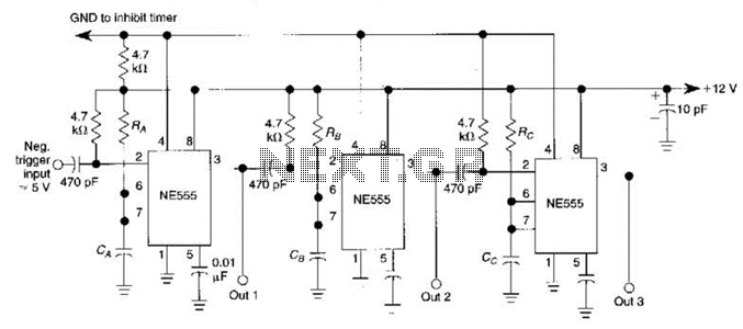
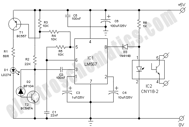
The circuit is designed around a 555 oscillator/timer, providing two distinct time periods. The longer time period can be adjusted between approximately 1 to 10 minutes, while the shorter time period is fixed at around three seconds. The operation...
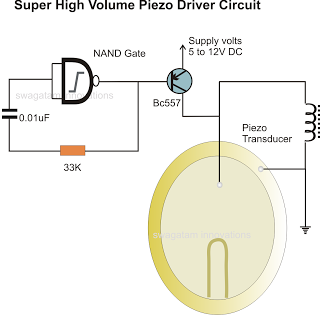
In the previous post, a piezo transducer element was discussed, along with its application in electronic circuits. This article will explore how a piezo transducer can be driven or operated using a simple circuit. The amplification method differs from...
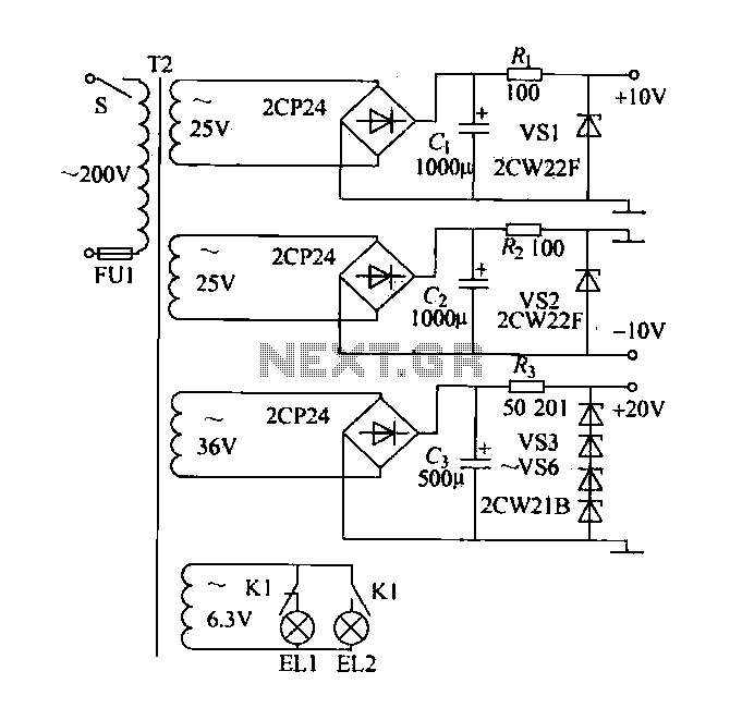
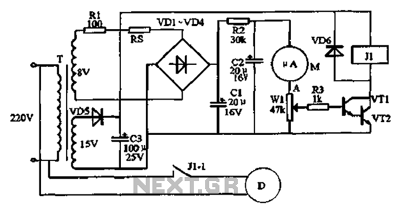
A DC power supply with a shunt, rectifier, filter, current limiting, and voltage regulation, providing 10V voltage outputs. The circuit is simple and low cost, designed to meet the requirements of various applications. Additionally, it features a 3V indicator...
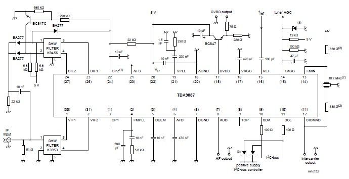
The integrated circuit (IC) is a multistandard vision and sound intermediate frequency (IF) phase-locked loop (PLL) demodulator that operates without the need for alignment. It supports multiple standards, including PAL, SECAM, and NTSC, and is capable of processing both...
This simple and economical infrared model train detector circuit is designed specifically for hobbyists who want to incorporate a smart sensor to detect trains on their model railway track. The schematic diagram illustrates a straightforward configuration comprising an infrared...
An automatic humidifier can be utilized for humidity control in households, hatcheries, poultry farms, or juvenile poultry houses. When the humidity level falls below 50%, the automatic humidifier activates to maintain a specific humidity level that is beneficial for...