
Parallel DC power supply circuit
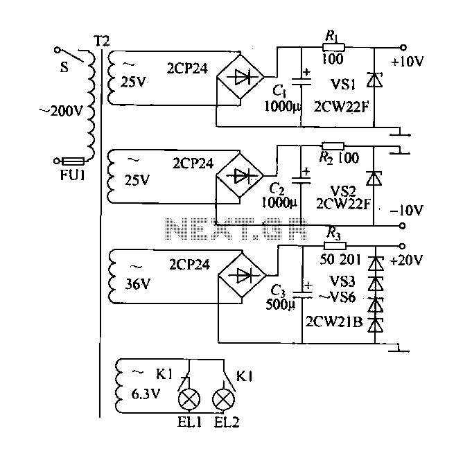
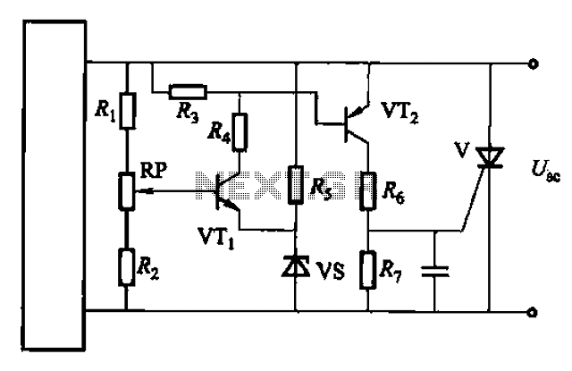
The DC power supply circuit is designed to convert alternating current (AC) to direct current (DC) while ensuring stable voltage output and adequate current limiting for safe operation. The shunt resistor is integrated into the circuit to measure current flow, enabling real-time monitoring and protection against overcurrent conditions.
The rectifier section utilizes diodes arranged in a bridge configuration to efficiently convert the incoming AC voltage to pulsating DC. Following the rectifier, a filter capacitor smooths the output voltage, reducing ripple and providing a more stable DC voltage.
Voltage regulation is achieved through a linear voltage regulator or a switching regulator, ensuring that the output remains at a constant 10V, regardless of variations in input voltage or load conditions. Current limiting is incorporated to prevent damage to the circuit components and the load by restricting the maximum current output.
The circuit also includes a 3V indicator system, comprising two indicator lights (EL1 and EL2), which signal the operational status of the machine. These indicators are controlled by a relay circuit that responds to the machine's operational state, illuminating EL1 when the machine is running and EL2 when it is stopped. This feature enhances user awareness and operational safety.
Overall, this DC power supply circuit is characterized by its simplicity, cost-effectiveness, and functionality, making it suitable for a wide range of applications in various electronic devices and systems.DC power supply with shunt, the rectifier, filter, current limiting, voltage regulation, 10V voltage outputs, the circuit is simple, low cost, to meet the requirements of vario us applications, as shown in FIG. FIG. 6. 3V indicator EL1, EL2, respectively, indicating the machine running and stopping, by the relay control circuit.
Related Circuits
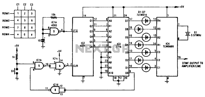
This circuit utilizes inexpensive, commonly available components to generate a precise dial tone for telephone applications. The Intel 82C54 timer-counter (U1) produces square wave signals at frequencies of 350 Hz and 440 Hz, which are subsequently filtered by resistors...
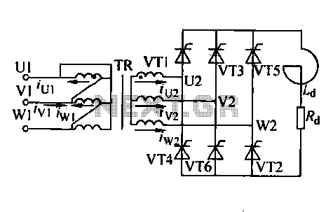
Trigger circuit routing forms include various types such as simple trigger circuits, single-junction transistor trigger circuits, synchronous sine wave trigger circuits, sawtooth transition phase shift (synchronous) trigger circuits, and integrated trigger circuits. This section presents individual cases for introduction...
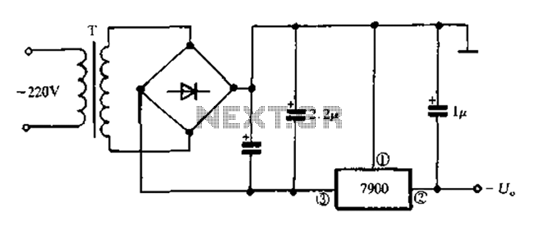
7900 series three-terminal fixed negative output voltage regulator circuit The 7900 series comprises a range of three-terminal fixed negative voltage regulators designed to provide stable output voltages. These regulators are specifically engineered to deliver a consistent output voltage, which is...
Both circuits are designed solely for overcurrent protection in power supply applications. The circuits in question serve as critical components in safeguarding power supply systems from overcurrent conditions. Overcurrent protection is essential in preventing damage to electrical components and...
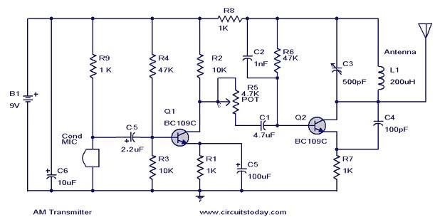
This document presents a circuit diagram of a simple AM transmitter that is capable of transmitting audio signals to a specified area. The circuit is designed with a limited power output to comply with FCC regulations while effectively producing...

Application of the differential amplifier circuit in OTL amplifier circuits. The differential amplifier circuit is a fundamental building block in various electronic applications, particularly in output transformerless (OTL) amplifier circuits. An OTL amplifier is designed to drive loads directly...
Warning: include(partials/cookie-banner.php): Failed to open stream: Permission denied in /var/www/html/nextgr/view-circuit.php on line 713
Warning: include(): Failed opening 'partials/cookie-banner.php' for inclusion (include_path='.:/usr/share/php') in /var/www/html/nextgr/view-circuit.php on line 713