
Collection of Crystal Oscillators


The circuits described utilize 3rd and 5th overtone crystals, specifically designed for frequencies ranging from 15 to 65 MHz and 60 to 105 MHz, respectively. These crystals operate in their series resonant mode, which is crucial for maintaining stability and accuracy in frequency generation. When the crystal is short-circuited, the oscillator is expected to function at or near the desired frequency, indicating that the circuit is properly designed.
In the operational phase, the inductor L1 plays a vital role in frequency tuning. It must be adjusted to achieve either a minimum voltage across the crystal or to precisely match the desired operating frequency. The ideal scenario is for these two tuning points to coincide; however, manufacturing tolerances often introduce discrepancies that necessitate careful adjustment and verification of the output frequency.
It is critical to avoid including a tuned circuit at the crystal overtone frequency within the collector circuit of transistor TR1. Such a configuration can lead to oscillations that are not controlled by the crystal, undermining the circuit's stability. Instead, a tuned circuit may be added at a frequency that is twice or three times that of the crystal, allowing for the extraction of harmonics from the collector, which can be beneficial for certain applications.
Transistor selection is also a key consideration in the design of these circuits. High DC gain (HFE) transistors with low base resistance (RBB) are recommended to ensure efficient operation. Additionally, the transit frequency of the chosen transistors should be at least ten times greater than the oscillator frequency to maintain performance and prevent distortion.
The circuits can accommodate various overtone crystals, with 3rd overtone crystals typically supplied for frequencies between 21 and 60 MHz, while 5th overtone crystals are available for frequencies ranging from 60 to 126 MHz and 7th overtone crystals for frequencies from 126 to 175 MHz. This flexibility allows for a wide range of applications in frequency generation and signal processing.On following pages circuits are shown for 3rd overtone crystals 15 to 65MHz and 5th overtone crystals 60 to 105 MHz operating in their series resonant mode. In both of these circuits with the crystal short circuited, the oscillator should operate at or near the required frequency.
With the crystal in circuit L1 should be adjusted for either (a) minimum voltage across the crystal or (b) for the exact frequency required. Ideally, these two points would coincide but they rarely will due to the need for a manufacturing tolerance on crystal frequency.
If L1 is of incorrect size it is possible for the oscillator to operate on a different order of overtone, for this reason it is important to accurately check the output frequency. Under no circumstances should a tuned circuit at the crystal overtone frequency be included in the collector circuit of TR1 as this configuration will result in oscillation not controlled by the crystal. However it is possible to include a tuned circuit at that point which is twice or three times the crystal frequency.
It is then possible to extract from the collector the harmonics of the crystal frequency. It is recommended that transistors for use in this circuit have a high DC gain (HFE) and a low base resistance (RBB). Also ensure that the transit frequency is at least ten times that of the oscillator frequency. Unless otherwise specified we supply 3rd overtone crystals between 21 and 60 MHz. 5th overtone between 60 and 126 MHz and 7th between 126 and 175 MHz. 🔗 External reference
Related Circuits

Can anyone provide guidance on a simple, usable circuit that can be constructed for testing crystals? Numerous circuits have been encountered during online searches. A simple crystal testing circuit can be designed using a few essential components, typically including a...
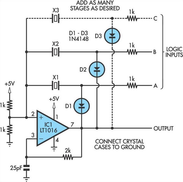
This oscillator circuit allows crystals to be electronically switched by logic commands. To understand the circuit, it is helpful to initially disregard all crystals and consider all diodes as shorts while their associated 1kΩ resistors are treated as open....

Utilize the Maxim MAX292 switched-capacitor filter integrated circuit to convert a square wave into a sine wave. The operational frequency range of the circuit spans from 5.2282 Hz to 8928.6 Hz when the microcontroller is functioning at a 16-MHz...
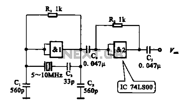
A crystal oscillator circuit comprises various gates as illustrated in the provided figures. Figure (A) represents a crystal oscillator circuit operating at 1 MHz, while figure (B) depicts a 20 MHz crystal oscillator circuit. Figure (C) shows a variable...
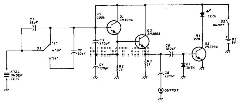
This circuit utilizes a Colpitts oscillator (Q1) paired with a buffer amplifier (Q2) to facilitate crystal testing. SI allows for the selection of three load conditions: series (S), 20 pF, and 32 pF. It is essential to keep the...
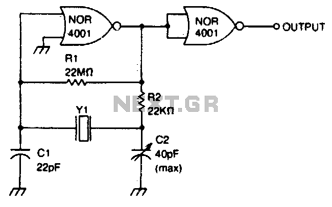
This circuit operates within a frequency range of 0 MHz to 2 MHz. The frequency can be finely adjusted to a specific value using the trimmer capacitor C2. Additionally, the second NOR gate functions as an output buffer. The circuit...