
original electric furnace

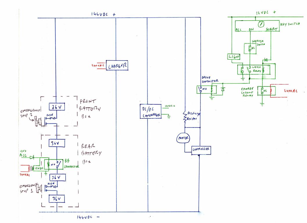
The switched system described utilizes a relay-based architecture rather than a sequencer, which is common in modern electric heating systems. This configuration can lead to simpler designs but may lack the efficiency and control offered by sequencers. The blower motor is integral to the system's operation, providing airflow necessary for heat distribution. The blower's 5-speed capability, although only two speeds are currently utilized, indicates potential for improved performance if the system were upgraded.
The circuit breakers (CB1, CB2, and CB3) are critical for safety and operational control, ensuring that each heating element and the blower motor can be independently managed. Circuit breaker 1 (CB1) is dedicated to the first two heating elements, which are typically activated during initial heating phases. Circuit breaker 2 (CB2) manages the middle two heating elements, while circuit breaker 3 (CB3) controls the last heating element and the blower motor, allowing for segmented control of the heating elements based on demand and safety protocols.
The operation of switch K1 is crucial, as it determines the blower's speed based on the thermostat's settings. When the thermostat calls for heat, the closure of K2 initiates low-speed operation of the blower, promoting efficient heat circulation while minimizing energy consumption during the startup phase. The activation of heating elements 1, 2, and 5 during this phase indicates a focus on rapid heat generation. The auxiliary contact of K2, which may close with a delay, suggests an intentional design to manage load transitions smoothly, preventing sudden spikes in current draw that could stress the system.
In summary, this system's design emphasizes relay control, segmented power management through circuit breakers, and a dual-speed blower operation, which collectively contribute to its functionality. Further enhancements, such as the addition of a sequencer, could optimize performance and improve energy efficiency. Understanding the interaction between the thermostat and the various switches is essential for diagnosing and optimizing the system's operation.This is a switched system, meaning it doesn`t have a sequencer like modern electric furnaces. Instead, relays are used. Maybe this is a good upgrade to make, installing a sequencer. The blower is a 5 speed blower, although only two seem to be used (unlike what the wiring schematic says): Low speed for startup, then high speed. 5 heat strips, or "element-electric heat", element 1&2 on circuit breaker 1 (CB1), element 3&4 on circuit breaker 2 (CB2), and element 5 + blower motor on circuit breaker 3 (CB3). Switch K1 drives the blower motor. This is the switch that is turned on when the thermostat manual switch is set to run the fan. If K1 is OFF, and K2 or K3 is on, then the blower runs at low speed. If K1 is ON, then the blower runs at high speed. I will have to research a bit more to understand how the thermostat drives the different switches. It looks like upon a call for heat, the thermostat will close K2, which will run the blower on low speed, and energize HE1, 2 & 5.
K2 AUX contact will close, possibly after a delay ( ), and energize K3, which will turn HE3 and HE4 on. 🔗 External reference
Related Circuits
This circuit is designed to detect electrical wires connected to the mains (live wire). It features an LED for visual indication and a buzzer for audio alerts. As the detector is brought closer to the electrical wire, the LED...
A Subaru Brumby has been in possession for an extended period. The mechanic has indicated that the engine is... The Subaru Brumby, a compact utility vehicle, features a robust engine that is essential for its performance and reliability. The engine...
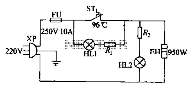
The 220V electric vibrator features a clip for insertion, with FU representing the fuse. ST indicates an inverter-like device, while HL1 and HL2 serve as indicators for insulation and heating. The EH component functions as the heater. When the...
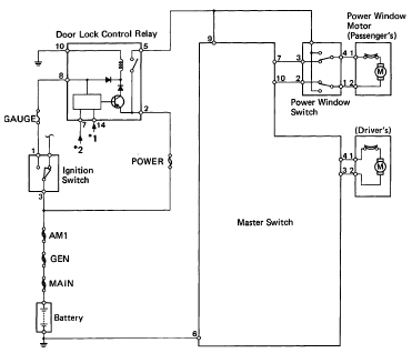
The following circuit illustrates the 1993 Toyota Hilux Pickup Power Window Control System Electrical Circuit Diagram. It is beneficial for both personal use and for mechanics during repairs. Key components include the door lock relay, junction block, power window...
Implementing tactile (haptic) feedback in consumer electronic devices enhances the user experience by providing a sense of touch in user interface design. It represents the latest major interface innovation in smartphones and other portable consumer electronic devices. Various haptic...
The primary application area for brushless direct current motors (BLDC) is in positioning systems. Brushless Direct Current (BLDC) motors are widely utilized in various positioning applications due to their high efficiency, reliability, and precise control capabilities. These motors operate without...