
Electrical Live Wire Detector

The wire detector circuit operates on the principle of electromagnetic field detection. The antenna, which is formed by T1, captures electromagnetic waves generated by the alternating current flowing through the live wire. Capacitor C1 plays a crucial role in filtering out high-frequency noise that may interfere with the detection process, ensuring that only relevant signals are processed.
After the initial filtering, the low-frequency signals are directed to the amplifier stage (T2). This stage amplifies the detected signals to a level suitable for further processing. The output from T2 is then passed through a pulse shaping filter, which is composed of resistors R10, R11, and capacitor C3, along with transistors T3, T4, and T5. This filter shapes the output signal into a pulse form, allowing for more precise detection of the presence of the electrical field.
In the final stage, T5 acts as a current amplifier, driving the LED or buzzer. This stage is critical for providing a clear visual and audible indication of the presence of live wires. The design allows for flexibility; either an LED or a buzzer can be used depending on the user's preference for indication type.
The circuit is powered by a 9V battery, which ensures portability and ease of use. The adjustment feature provided by potentiometer P1 allows the user to calibrate the sensitivity of the detector. By rotating P1 to the left, the circuit is set to its most sensitive state, enabling it to detect even weak signals from distant live wires. The push-button serves as an activation mechanism, allowing the user to initiate the detection process conveniently.
Overall, this wire detector circuit is a practical tool for electricians and DIY enthusiasts, providing a reliable means of identifying live electrical wires safely.This circuit can detect only electrical wires connected to the mains (live wire). It has an LED for visual signalization and a buzzer for audio. As the electrician places the detector closer to the electrical wire the LED will flash at a higher frequency. As you can see the schematic of the wire detector circuit is quite simple. The first stage ha s the antenna in base of T1; capacitor C1 is used for filtering parasite high frequency signals which are captured by the antenna. The low freq signal is captured through C4 and is applied to the amplifier stage (T2) and then to the pulse shape filter made with R10, R11, C3 and T3, T4 and T5.
The final stage (T5) is a current amplifier for the LED or you can place a buzzer too. Connect the 9V battery and place the circuit close to a electrical wire that is connected to the main volage. Adjust P1 rotating the cursor to the left completely. Press the push-button and the LED should start flashing. Now adjust P1 until LED is dim. In this moment the detector circuit is set to maximum sensitivity. 🔗 External reference
Related Circuits
This is a circuit which I originally included in my book, 22 Tested Transistor Projects, published by Babani Press in 1976 (ISBN 0 900162 63 S). It is one I had great fun with. It uses the PUT Complimentary...
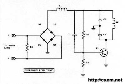
Wireless Telephone Bug. This project enables monitoring of a phone line as soon as the phone is off-hook. A regular FM broadcast band radio can be utilized for this purpose. The Wireless Telephone Bug is a circuit designed to allow...
This metal detector utilizes the CS209A integrated circuit manufactured by Cherry Semiconductor. The CS209A is a bipolar monolithic IC designed for metal detection and proximity sensing applications. It features two on-chip current regulators, an oscillator, low-level feedback circuits, a...
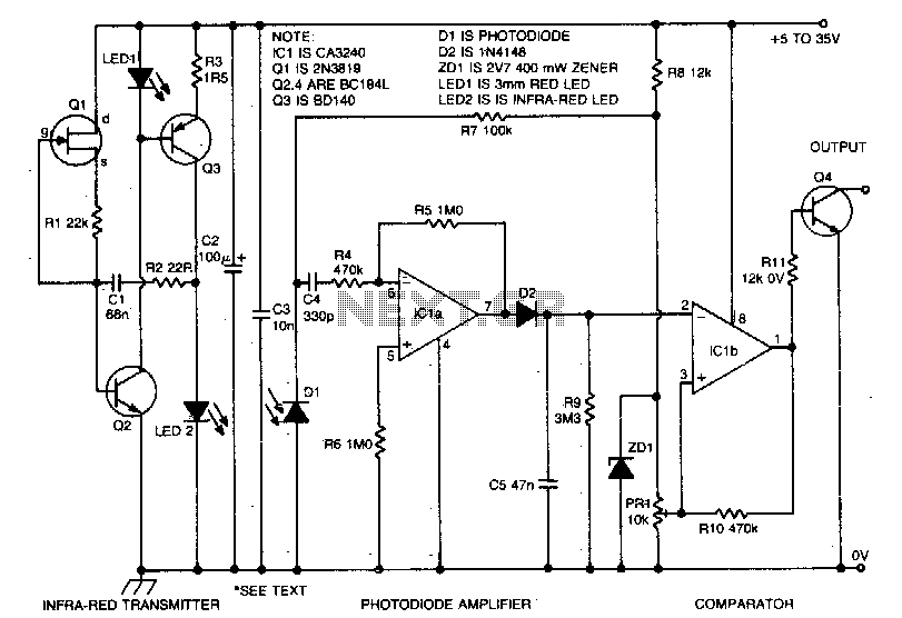
The proximity sensor operates on the principle of emitting a beam of modulated infrared light from the LED2 emitter diode and detecting reflections from objects that come into the path of the beam using a photodiode detector, Dl. The...
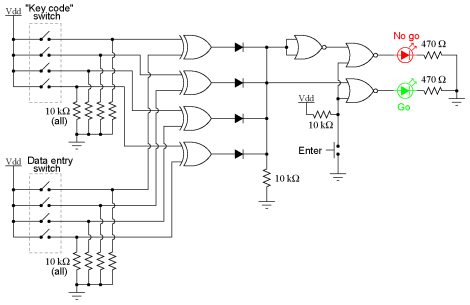
This experiment can be constructed using a single 8-position DIP switch, although utilizing two switch assemblies may facilitate a better understanding of the concept. One switch assembly is designated to hold the correct code for unlocking the lock, while...

This circuit was designed to detect when a call is incoming in a cellular phone (even when the calling tone of the device is switched-off) by means of a flashing LED. The device must be placed a few centimeters...