
Tactile feedback solutions using piezoelectric actuators
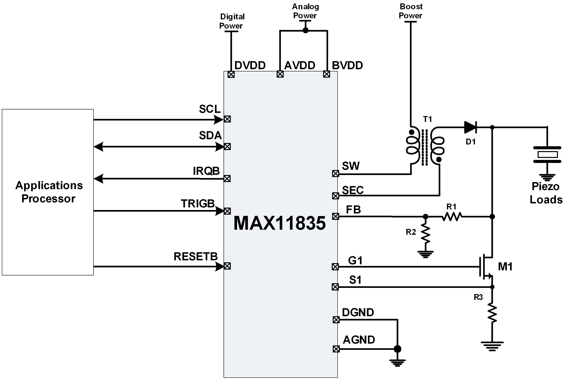
Traditionally, one of the challenges associated with piezo-based haptics has been the complexity of the solution. Typical piezo-based systems have employed discrete components to create a complete tactile feedback system, including a microcontroller, flyback boost or charge-pump integrated circuit, flyback transformer or inductor, along with various resistors, capacitors, diodes, and transistors. In contrast, DC motor-based haptics often require fewer or no external components. A single-chip monolithic haptic solution, such as the MAX11835, presents several advantages over older discrete designs: a smaller printed circuit board (PCB) footprint, reduced power consumption, lower bill-of-materials (BOM) costs, and simplified software support. When combined with the low profile of piezo actuators, the MAX11835 emerges as an appealing option for portable handheld devices.
Piezo actuators inherently consume less power compared to DC motor actuators. However, additional power considerations must be taken into account. Power consumption measurements were conducted on various piezo actuators and high-voltage capacitors utilizing the MAX11835 haptic actuator controller. The MAX11835 reproduces a stored waveform through a software-controlled flyback boost converter in a feedback loop. The test waveforms included a 100Hz sine wave and a 20Hz ramp. The peak boost power-supply current versus load was evaluated under specific test conditions: frequency = 100Hz sine wave; boost power-supply voltage = 4.2V; boost supply decoupling = 10 µF; 6:1 transformer. A common feature is the button press, where the waveform depicted in Figure 10 illustrates a 40ms charge followed by a 10ms discharge. The gradual charge is imperceptible to touch, while the rapid discharge simulates the feeling of a mechanical button being pressed.
In Figure 11, the waveform is continuously active, with power scaling down linearly as the duty cycle decreases. No significant difference in piezo data was observed between a mechanically loaded (at half-blocking force) and an unloaded piezo actuator. Figure 11 also presents a plot of power versus piezo voltage, showing that the rapid increase in power above 180V occurs when the primary clamp in the MAX11835 activates. Figure 12 illustrates the efficiency of the MAX11835's boost process, measured as the energy delivered to the load versus the energy drawn from the boost power supply (VBST). The efficiency increase above 180V is similarly attributed to the activation of the primary clamp in the MAX11835. The power consumption of the MAX11835 is competitive with motor-based actuators, including eccentric rotating mass (ERM), linear resonant actuator (LRA), and voice-coil types. Motor-based actuators typically operate at low voltages (1.8V to 3V), but they can draw relatively high currents.Implementing tactile (haptic) feedback in consumer-electronic devices enhances the user ’s experience. It provides a sense of touch in a user-interface design and is the newest major interface on smartphones and other portable consumer-electronic devices.
Several haptic technologies are available now, including but not limited to vibration motor actuation, piezoelectric actuation, and electro-active polymer actuation. This article explains the basics of piezoelectric-based actuation and how it offers a fast response time, thin profile, and low power, all of which are important in handheld applications. The information from Table 1 suggests using single-layer piezo actuators. They are more available and already in production volumes; multilayer piezos, while in production, are less available.
Also, a single-layer piezo costs much less, a factor that becomes more important in solutions with more than one piezo. For example, several smartphones on the market have multiple single-layer discs mounted behind the display.
A similar multilayer piezo solution would cost considerably more. One of the drawbacks of piezo-based haptics has traditionally been the complexity of the solution. Typical piezo-based solutions have used discrete components to implement the complete tactile feedback system; the extra discrete components included a microcontroller, flyback boost or charge-pump integrated circuit, flyback transformer or inductor, miscellaneous resistors, capacitors, diodes, and transistors. Compare that with DC-motor-based haptics which require few or no external components. A single-chip monolithic haptic solution such as the MAX11835 has several advantages over the older, discrete designs: smaller printed circuit board (PCB) footprint, lower power, lower bill-of-materials (BOM) cost, and simple software support.
Couple this with the low profile afforded by piezos, and the MAX11835 becomes an attractive solution for portable handheld devices. Piezo actuators by themselves require very little power compared to, for example, DC motor actuators.
Nonetheless, there are other power factors to consider: Power-consumption measurements were performed on various piezo actuators and high-voltage capacitors using the MAX11835 haptic actuator controller. The MAX11835 plays back a stored waveform using a software-controlled fly-back boost converter in a feedback loop.
The test waveforms include a 100Hz sine wave and 20Hz ramp. Figure 9b: Peak boost power-supply current vs. load. Test conditions: frequency = 100Hz sine wave; boost power-supply voltage = 4. 2V; boost supply decoupling = 10 µF; 6:1 transformer. A button press is a common feature. The waveform in Figure 10 uses a 40ms charge, 10ms discharge. The slow charge is imperceptible to the touch, and the rapid discharge feels like a mechanical button being depressed. In Figure 11 the waveform is continuously running. The power scales down linearly as the duty cycle is reduced. There was no obvious difference in the piezo data between a mechanically loaded (at half-blocking force) and an unloaded piezo actuator.
Figure 11: Power vs. piezo voltage plot. Emulated button press using single and multiple disc piezos. The rapid increase in power above 180V is caused when the primary clamp in the MAX11835 turns on. Figure 12 presents the efficiency of the MAX11835 ’s boost process, measured as energy delivered to the load and the energy drawn from the boost power supply (VBST). Figure 12: Energy transfer efficiency: energy stored on load and energy drain in VBST. The rapid increase in efficiency above 180V is caused when the primary clamp in the MAX11835 turns on.
Power consumed by the MAX11835 compares favorably with motor-based actuators, including eccentric rotating mass (ERM), linear resonant actuator (LRA), and voice-coil types. Motor-based actuators typically require low voltages (1. 8V to 3V), but the currents can be fairly large 🔗 External reference
Related Circuits
The integrated output amplifier presented in this article consists primarily of a single integrated circuit. It is specifically designed for application in motor vehicles and other battery-operated devices. Despite its seemingly simple design, the amplifier is capable of delivering...
The maximum charge voltage is set at 1.45 volts, while the higher trigger threshold is approximately 1.7 volts. This voltage can be adjusted using potentiometer P1 to reach 1.45 volts. A TTL control signal is output by the voltage...
Doug Grant's article on Heathkit in his blog via the EDN Network reflects on his experience building his first Heathkit and the knowledge he gained. He suggests that every electrical engineer has built at least one kit, a notion...
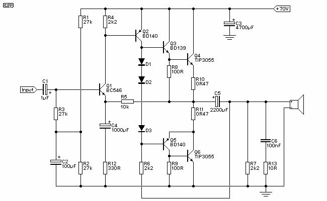
Figure 1 shows the circuit. A major change from all of the designs from that era is the speaker coupling capacitor - 1000uF (for a -3dB of 20Hz and a 8 Ohm load) was the most common value. This is...
This circuit is designed to drive a total of 42 LEDs, assuming a forward voltage of approximately 2.2V per LED and a forward current of around 21mA for adequate brightness. If the specifications of the LEDs differ significantly, modifications...

Voltage regulator ICs (78xx series) provide a steady output voltage, in contrast to a widely fluctuating input supply, when the common terminal is grounded. The 78xx series of voltage regulator integrated circuits (ICs) are widely utilized in electronic circuits to...