
OSA Link Cable Schach computer
The circuit design for connecting the SciSys Leonardo and Saitek chess computers to a PC involves a few key components and connections that ensure proper communication between the devices. The TTL-RS232 converter IC, such as the MAX 232 or ADM232L, is central to this design, enabling the conversion of signals between the TTL logic levels used by the chess computers and the RS232 levels used by standard serial ports on PCs.
The circuit requires a stable power supply, which is provided by the 5V regulated output from the OSA interface. The 9V unregulated output can be omitted if using the MAX 232 or ADM232L, as these ICs are designed to operate solely on 5V. The inclusion of five 1 µF capacitors is necessary for the ADM232L to ensure stable operation, while the MAX 232 typically requires four capacitors of varying values for proper signal conditioning.
The connections to the chess computer are made through a 5-pin DIN connector, which must be wired correctly to match the pinout of the OSA interface. The PC side utilizes a 9-pin Sub-D connector, which connects to the serial port of the computer. If the computer does not have a serial port, a USB-to-RS232 adapter can be used instead, allowing for modern compatibility.
Additional attention must be given to the orientation of electrolytic capacitors, as incorrect placement can lead to circuit failure. Clear markings on the circuit board guide the correct orientation for these components.
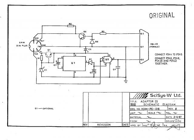
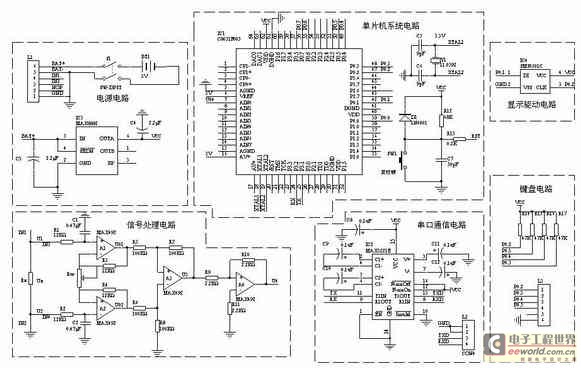
Overall, this schematic design provides a reliable method for interfacing legacy chess computers with contemporary PCs, ensuring that users can continue to enjoy these classic devices with modern software tools. Proper assembly and connection verification are crucial to achieving a functional setup.The SciSys Leonardo and Saitek Galileo and Renaissance chess computers could be connected to a PC via an OSA-Link cable. Such a cable is needed to run the OSA-4-Arena software and other tools. Unfortunately that cable is no longer available. Special information can be found in the manual `Connection Cable for Leonardo Chess Computer`, published fr
om Saitek in 1987. It is available as download at look under Documentations and Saitek. The pictures above are taken from this specification. On the PC side (right) only GNG, RxD and TxD are connected. The OSA interface (left) has GND, RxD, TxD, 5V (regulated) and 9V (unregulated). Both voltages are needed by the TTL-RS232 converter MC1488P. The IC on the left (yellow circle) is a regulator for the 9V from the OSA interface. The next picture shows the original circuit diagram. Is is relative easy to re-assemble an OSA-cable. You will need a modern IC for the TTL-RS232 conversion and two cables, one with a 5-pin-DIN male jack and the other with a 9-pin female RS232 socket. As IC you can take the well known MAX 232 or an ADM232L. Both ICs need only 5V to operate, so the 9V from the board is not needed and will make the work easier.
For the ADM232L you will need 5 condensers with 1 F each, that`s all. The IC has two communication lines (T1/R1 and T2/R2), for OSA only one will be used. You can choose any of these ICs and assemble your own circuit, but it will be much easier to buy a ready-to-go assembly kit. A fellow at found a very nice kit at, a german electronic distributor. It is still possible to order the kit from foreign countries. The Sub-D cable is for the connection from the adapter to the PCs serial interface and optional, if you don`t have one.
If your PC or Laptop does not have a serial interface, you can use an USB-to-RS232-adapter (not available at Pollin). The 5-pol. -DIN cable is for the connection to your chess computer. One of the plugs will be cut off and the single cables will be plugged into the clamp of the Pollin adapter.
The connectors for the TTL-cable and the RS232 jack are self-descriptive. At the bottom of the picture you see a condenser of 100 nF (C5), the fitting direction doesn`t matter. The condensers on the left with 10 F have a plus/minus orientation. It is important to fit them in the right orientation to the circuit. Plus is marked on the board with a + and minus with a bold-white line (see C1 to C4). The condensers are marked with a coloured line and the number 0 in it for the minus pole. The PC side is now still ready and you can connect a 9-pol-Sub-D cable to the left. For the chess board side only the above four connections are needed (5V, GNG/Masse, TxD, RxD). Take the 5-pol-DIN cable, cut off one plug and strip the wires. Then check which wire (different colour) is connected with what pin at the DIN-plug. Check that the plug is in the correct orientation with the OSA-plug layout. The wire to pin 4 is not used and can be cut off. The colours may vary from manufacturer to manufacturer, even if you buy it from the same vendor. So please check the cable connections carefully! To fit the wired into the plugs of the circuit board it is a good idea to fold the ends. This will give a more stable connection in the screwed plugs. Do not tin-plate the wires with solder, just use the copper wires as they are. Fit 5V (white) into the right plug and GND (yellow) in the second plug. RxD (red) shall be fit into the TxD-plug and TxD (blue) shall be fit into the 4th plug (RxD) of the circuit board.
🔗 External reference
Related Circuits
The signal is encoded as a pair of sine waves, ensuring that no frequency is a multiple of the other, and that the sum and difference between the two frequencies do not match any single tone, which contributes to...
VIC-20CR rev. D (NTSC, new design). Assembly number 251027-01. The PAL model operates at a crystal frequency of 4.433618 MHz and includes an additional 56pF capacitor on the solder side of the board, connected in parallel with R5. The VIC-20CR...
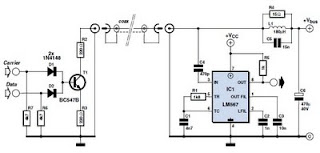
This circuit was designed to transmit commands over an LNB coaxial cable. An LNB (Low-Noise Block downconverter) is commonly used for satellite TV reception and is positioned at the focal point of a satellite dish. The circuit generates a...
A one-chip computer has been utilized to design this survey meter, which directly displays the measured resistance on an LCD screen. The measurement range extends from 0 to 9999 kΩ, and the device can simultaneously store the measured data,...
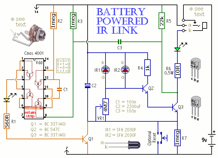
When a remote control signal is received, the energy stored in C2 drives the emitter diode. At the same time, Q1 switches on briefly to allow the battery to recharge C2. The green LED shows that the circuit is...
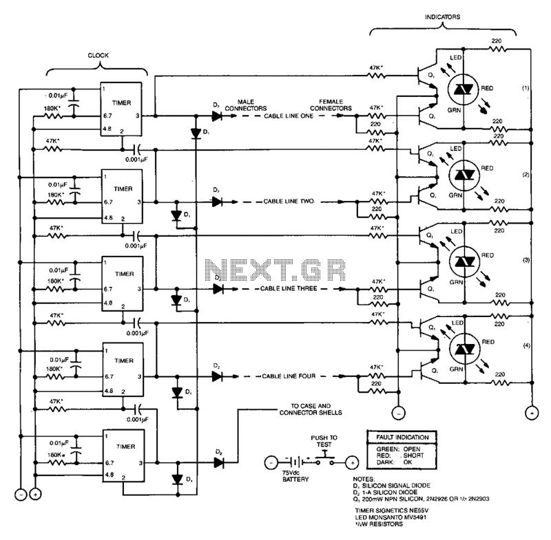
This compact tester checks cables for open-circuit or short-circuit conditions. A differential transistor pair at one end of each cable line remains balanced as long as the same clock pulse generated by timer IC appears at both ends of...