
IR Link
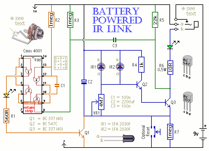
The described circuit operates as a remote control signal receiver that utilizes a capacitor (C2) to store energy for driving an emitter diode. The emitter diode is responsible for transmitting a signal, while the transistor (Q1) plays a critical role in managing the power supply to C2. When a remote control signal is detected, Q1 is briefly activated, allowing the battery to recharge C2, thereby ensuring that the circuit remains functional and capable of transmitting signals consistently.
The visual indicators in the circuit include a green LED, which illuminates to indicate that the circuit is actively transmitting, and a yellow LED, which serves to confirm that C2 has been adequately recharged. This dual LED indication provides clear feedback on the operational status of the circuit.
To address the issue of unwanted infrared (IR) radiation interference, particularly in environments with daylight or tungsten lighting, the design incorporates strategies to minimize this effect. An opaque housing is recommended to shield the internal components from extraneous light. The dimensions of the opening for the signal receiver are specified to be a horizontal slot measuring 2 cm by 1.5 cm, which helps to limit the amount of ambient light that can interfere with the operation of the receiver diodes.
Furthermore, the design suggests that the receiver diodes be mounted side-by-side within the case, positioned a few centimeters deep. This arrangement is intended to create additional shading for the diodes, further protecting them from potential IR interference. However, the specific depth required for effective shading is not detailed, indicating that further experimentation may be necessary to optimize performance under varying lighting conditions. This circuit design illustrates a thoughtful approach to managing both power efficiency and interference mitigation in remote control applications.When a remote control signal is received, the energy stored in C2 drives the emitter diode. At the same time, Q1 switches on briefly to allow the battery to recharge C2. The green LED shows that the circuit is transmitting; and the yellow LED confirms that C2 has been topped-up. There is unwanted IR radiation in both daylight and tungsten lighting. To minimize its effect use an opaque housing and do not make the opening too large. (Try a horizontal slot measuring 2 cm X 1.5 cm.) Shade the receiver diodes by mounting them side-by-side a few centimetres deep, inside the case. The depth of shading requ 🔗 External reference
Related Circuits
The circuit involves powering an LED using a 3V CR2032 battery, with the intention of extending battery life by making the LED blink rather than remain continuously on. A 555 timer is considered, utilizing large value resistors in the...
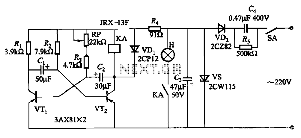
The circuit features a self-excited multivibrator composed of transistors VTi and VTZ. It includes an adjustment potentiometer RP and two RC networks that influence the transistors' parameters, specifically the timing for light activation and deactivation. The described multivibrator circuit utilizes...
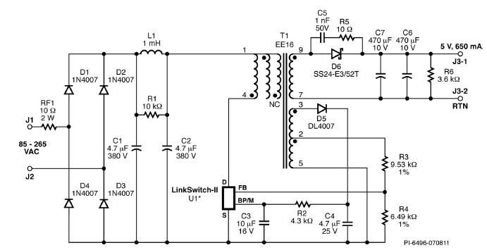
A simple 3.25W constant voltage/constant current (CV/CC) charger can be designed using the LinKSwitch family IC manufactured by Power Integrations. This electronic circuit project is intended to provide a 5-volt output with a maximum current of 650mA. The 3.25W...
A pulsating light is used for signaling purposes with a voltage of 230V. A simple circuit has been designed, consisting of an LED diode, two capacitors, two resistors, a diac, and a diode. The operation of the circuit is...
This circuit initiated the development of various Link Telephone Intercom designs. Originally created in 1996 using heavy-duty relays and contact banks, it was updated last year by replacing a simpler transistor multivibrator with IC1, substituting all relays and contact...
As before, there are two sections: the transmitter board and the receiver board, both powered by a separate 9V battery or a fixed voltage power supply, depending on your needs. The transmitter board has an electret microphone module at...