
Oscillator circuit schematic
The radio transmitter unit for the Cirrus One rocket mission was designed to address potential recovery issues associated with high-altitude launches. The transmitter was implemented to function as a homing beacon, utilizing the signals generated by the onboard altimeter. The altimeter was intended to produce a continuous beeping sound upon reaching peak altitude, which would be captured by the transmitter. This feature was crucial for recovery operations, especially given the risk of the rocket drifting due to wind conditions during ascent.
The FRS radio selected for this application, the Panasonic "Talkabout FR50," operates within the designated frequency band of 462.5625 MHz to 467.7125 MHz. The radio's inherent characteristics and affordability made it a suitable choice for this project. The modifications made to the unit were minimal, primarily involving the removal of the protective casing and the rubber antenna cover, while the battery holder was retained for functionality.
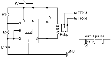
A significant challenge arose due to the radio's built-in power-saving feature, which would deactivate transmission if the transmit switch was engaged for longer than one minute. To circumvent this limitation, a 555 timer-based oscillator circuit was designed. This circuit was responsible for periodically activating a relay that controlled the transmitter, ensuring that it would transmit intermittently, thereby preventing the unit from shutting down. The timer circuit was constructed using specific resistor and capacitor values, resulting in calculated time constants that allowed for a brief interruption in transmission, thereby resetting the timer and maintaining continuous operation.
The antenna was strategically mounted along the longitudinal axis of the rocket's fuselage, which was constructed from PVC plastic. This orientation was chosen to minimize any potential signal loss during transmission. The transmitter unit was securely housed within a payload cradle, which also accommodated the altimeter and the oscillator circuit along with their respective power supplies. The cradle was fabricated from lightweight aluminum materials to ensure structural integrity while minimizing additional weight.
To facilitate operational access, ports were created in the fuselage to allow for manual control of the transmitter's rotary power switch and the oscillator's DIP switch. This design consideration ensured that the unit could be easily activated prior to launch, while also maintaining the integrity of the rocket's structure. Overall, the integration of the radio transmitter within the Cirrus One rocket exemplified a practical approach to addressing recovery challenges associated with high-altitude launches.This web page describes the radio transmitter unit that flew aboard the Cirrus One rocket in April 2001. The intent of including the transmitter as payload was to: As the Cirrus One rocket was expected to achieve an altitude that would be well out of visual range at 10, 000 feet (3 km.
), it was felt that there could be recovery difficulties if the wind (if present at launch) would carry the rocket far downrange. Since the altimeter that also flew with the rocket was expected to generate a continous audible "beeping" code once peak altitude was achieved, this sound could be picked up by the transmitter and effectively act as a homing beacon*. Although of secondary importance, it was felt that it might be advantageous to receive the altimeter signal of peak altitude while the rocket was still in flight.
just in case the recovery system should fail to function properly, or if the rocket was to be otherwise lost. This was my first try at having a transmitter as payload, and I felt that an FRS radio might be a practical, simple, and inexpensive solution that could be implemented within the short timeframe that was available prior to the launch event.
* As it turned out, a software bug dictated last-minute replacement of the altimeter`s PIC chip with one with updated software, which, unfortunately, provided for only a one time, rather than continous, audible broadcast of the coded peak altitude. The transmitter unit was an essentially unaltered FRS radio transceiver. These inexpensive units, which operate at a frequency band of, 462. 5625 MHz to 467. 7125 MHz, have an advertised range of 2 miles (3. 2 km. ). The unit that I used was a Panasonic "Talkabout FR50", with 14 channels, and cost about $30 CAD. The only modifications to the unit involved stripping away the case and rubber antenna cover. The battery holder (3 AA cells) was retained, however. The only other modification that proved to be necessary was the interfacing of the unit to a simple oscillator circuit.
This FRS unit (and others I investigated) had a built-in "power-saver" feature, that would cease transmission if the transmit switch was held on for greater than one minute. This obviously made the unit useless for its intended purpose. So I came up with a simple solution, a 555 timer based oscillator circuit that would continually activate a relay, except that once every minute or so the relay would deactive briefly, just long enough to break the one-minute continuous transmit limitation.
The circuit is shown below in Figure 2. The circuit components were mounted on a small 3 cm x 4 cm piece of Veroboard. The values of the resistors and capacitor were R1=1. 05 Meg ohm, R2=13. 8 k ohm, and C1=47 microF, which provided time constants of approximately t1=34 seconds and t2=0. 5 seconds, with the time constants given by t1=0. 693 (R1+R2)C1 and t2=0. 693 (R2)C1. Note that the antenna was mounted along the rocket longitudinal axis, inside the fuselage. As the fuselage was PVC plastic, no significant signal loss was expected. The transmitter unit, mounted in its payload cradle, is shown in Figure 3. The payload cradle, which also served as a mounting platform for the altimeter and oscillator circuit (and associated power supplies), is illustrated in Figure 4. Figure 4 - Cradle assembly for mounting the altimeter (top compartment), transmitter and oscillator circuit (bottom compartment) in the Cirrus One rocket.
Fabricated from 0. 063" 5052 aluminum alloy sheet and 1/8" 5356 aluminum alloy (welding) rod. In order to provide access to the channel select switch and display, a 3/4" diameter port hole was made in the fuselage wall (prior to flight, the hole was covered with a circular piece of aluminum tape). To turn on the transmitter`s rotary power switch and also the power switch (DIP) for the oscillator, two 1/8" diameter holes were also drilled through the fuselage wall, to allow a small rod to be inserted.
Just 🔗 External reference
Related Circuits
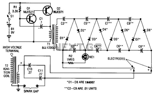
This circuit employs a transistor oscillator and a voltage multiplier to charge capacitors CIO and CI1 to a high voltage. When the spark gap breaks down, T2 generates a high-voltage pulse through the discharge of capacitors CIO and CI1...

This circuit includes a 2048 radio remote control transmitter and a corresponding wireless receiver that features high reception sensitivity and low power consumption. The combination of these two components provides a highly reliable remote control system, suitable for various...

This light alarm schematic circuit is designed using common electronic components, as illustrated in the circuit diagram below. The light alarm circuit will activate an alarm as soon as the drawer is opened and light falls on the Darlington...
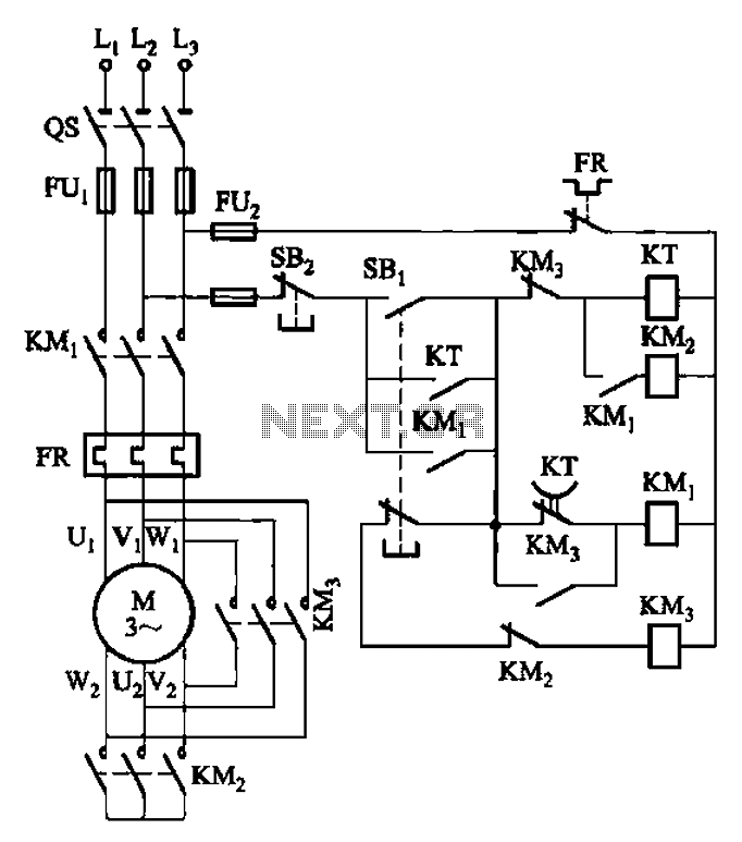
The circuit depicted in Figure 3-41 illustrates a Y-transfer process. When contact KMi is turned off, the motor undergoes a transition in the event of a power failure. Additionally, the main contact KM3 is disconnected when KM2 is activated,...
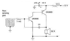
This rain detector electronic circuit project is a simple alarm circuit that activates an audio warning when liquid is detected on the sense pad. The circuit diagram is based on two transistors. When the sense pad conducts, transistors Tr1...

The water sensor circuit utilizes a 555 timer configuration along with standard electronic components. It consists of two metal electrodes positioned closely enough that a drop of water can create a conductive bridge between them. In cases where the...
Warning: include(partials/cookie-banner.php): Failed to open stream: Permission denied in /var/www/html/nextgr/view-circuit.php on line 713
Warning: include(): Failed opening 'partials/cookie-banner.php' for inclusion (include_path='.:/usr/share/php') in /var/www/html/nextgr/view-circuit.php on line 713