
Rain detector electronic circuit project
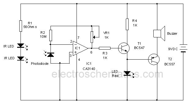
The rain detector circuit operates by utilizing two transistors configured in a feedback loop to create an oscillator. The sense pad, which is the primary sensing element, is designed to detect the presence of liquid. It can be fabricated using conductive materials on a printed circuit board (PCB) to ensure proper sensitivity and reliability.
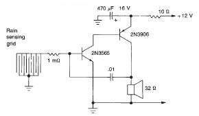
Upon contact with liquid, the sense pad completes the circuit, allowing current to flow through Tr1 and Tr2. This leads to the generation of an oscillating signal that drives a connected speaker, producing an audible alarm. The frequency of the oscillation can be adjusted by changing the values of the resistors and capacitors in the circuit, thereby allowing customization of the pitch of the sound emitted.
The power supply for this circuit is specified at 12 volts, which is standard for many electronic applications, ensuring compatibility with various power sources. The choice of a 32-ohm speaker is critical for achieving optimal sound output, as it matches the circuit's output characteristics and ensures efficient energy transfer.
In summary, this rain detector circuit is an effective and straightforward solution for alerting users to the presence of rain or liquid. Its design simplicity, combined with the ability to customize sound output, makes it suitable for various applications, including home automation and weather monitoring systems.This rain detector electronic circuit project is an very simple alarm circuit, that will start an audio warning, if the liquid is present on the sense pad. This rain detector electronic circuit diagram is based on two transistors. When the sense pads conducts, Tr1 and Tr2 from an audio oscillatory circuit that will generate a pitch sound.
Th is circuit needs a 12 volts power supply circuit and the speaker needs to have a 32 ohms. The sense pad can be constructed on a small piece of printed circuit board. 🔗 External reference
Related Circuits
The current feedback operational amplifier maintains a consistent bandwidth even when the open-loop gain is altered. This characteristic makes it particularly suitable for applications in video signal amplification and the driving circuits of video cables. The accompanying diagram illustrates...
Hello everyone, please examine this circuit. I constructed it recently, but it is not functioning. I have verified all connections and components, and everything appears to be in order. However, when I power it on... The circuit in question appears...
In the first circuit, the BC548 transistor is configured as a Colpitts oscillator, with the frequency being adjusted through the use of a crystal. A high-quality crystal will produce high-frequency oscillations, and the output at the collector is rectified...
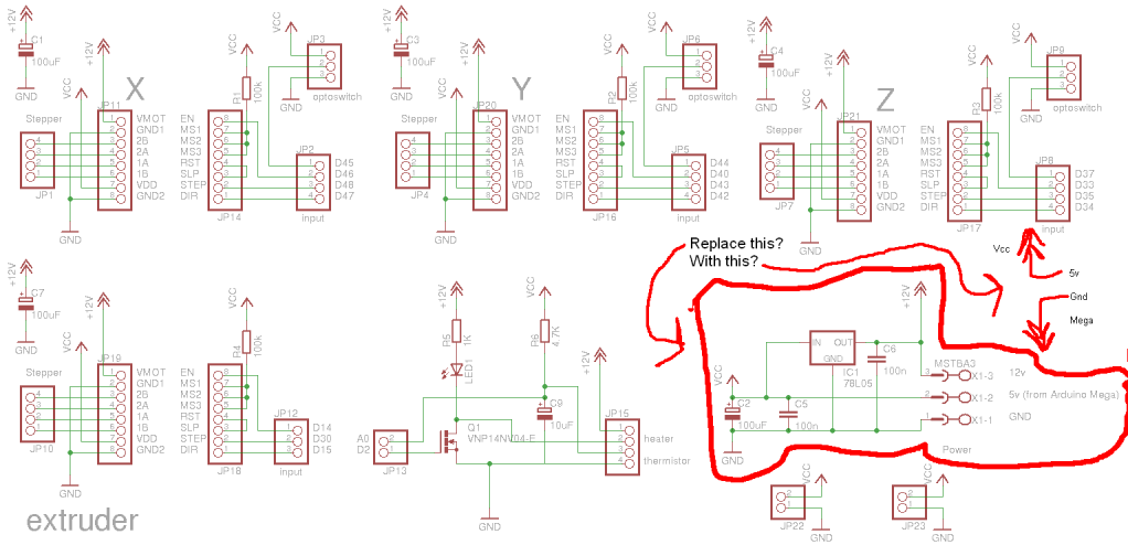
Preparing to assemble Adrian's Pololu stepper driver circuit has raised a question. He indicates that if using 5V from the Arduino Mega, the 78L05 voltage regulator should be omitted. This is a positive development, although there is an incorrect...

The R-C twin-tee passive circuit provides band-reject (notch) filtering suitable for portable applications. It has a loaded circuit Q of 0.25. Effective rejection is achievable when the bridge is balanced, which requires close tolerances of the adjustable components, and...
This circuit utilizes invisible infrared light to detect the movement of individuals through a doorway. A brief beep will be emitted when the infrared beam is interrupted. The infrared movement detection circuit employs an infrared LED and a photodiode or...
Warning: include(partials/cookie-banner.php): Failed to open stream: Permission denied in /var/www/html/nextgr/view-circuit.php on line 713
Warning: include(): Failed opening 'partials/cookie-banner.php' for inclusion (include_path='.:/usr/share/php') in /var/www/html/nextgr/view-circuit.php on line 713