
Oscillator interfaces data for tv
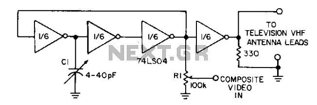
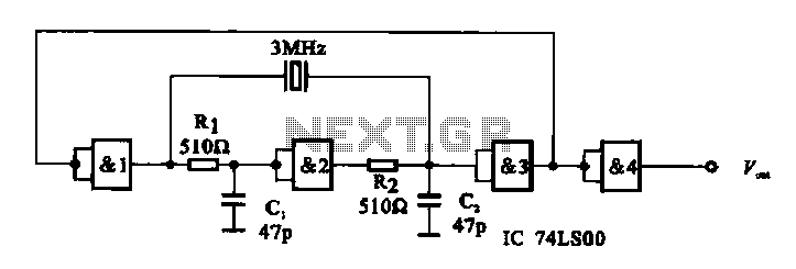
The circuit utilizes three inverters from the 74LS04 hex inverter IC to create an oscillator configuration. The frequency of oscillation is primarily determined by the external capacitor C1 and the resistors associated with the circuit. The capacitor is essential for tuning the circuit to resonate at the desired frequency, which corresponds to a specific television channel. This fine-tuning capability is crucial for optimal signal reception and stability.
The inclusion of potentiometer R1 serves dual purposes. As a variable resistor, it allows for the adjustment of the mixing input to the circuit. This adjustment affects the contrast ratio, which is vital for enhancing the visual quality of the output signal. By manipulating R1, users can achieve the best possible viewing experience, ensuring that the picture quality is clear and well-defined.
The fourth gate within the 74LS04 acts as a buffer, providing additional stability to the oscillator circuit. Buffers are critical in preventing signal degradation and ensuring that the oscillation remains consistent and reliable. The buffering action helps to isolate the oscillator from any variations in load or supply voltage, which could otherwise affect performance.
Overall, this configuration of the 74LS04 not only facilitates the generation of a stable oscillating signal but also incorporates features that enhance user control over the output quality, making it suitable for applications in television signal processing.Three gates of a 74LS04 form the oscillator circuit. Capacitor Cl allows fine-frequency adjustment to a specific television channel and helps stabilize the circuit. Potentiometer Rl acts as the mixing input and provides adjustment of the contrast ratio for the best viewing.
A fourth gate buffers and helps stabilize the oscillator. 🔗 External reference
Related Circuits
The oscillator employs a fundamental quartz crystal, capable of achieving an oscillation frequency of up to 10 MHz. The oscillator circuit is calibrated to the resonant frequency of the crystal. A capacitor, designated as C, with a value of...
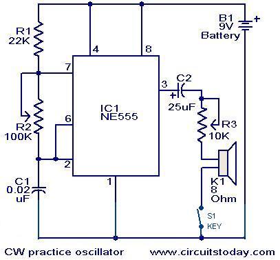
A circuit diagram for generating continuous wave (CW) Morse code is presented here. This circuit is particularly beneficial for individuals interested in practicing Ham Radio. It consists of an astable multivibrator utilizing the NE555 timer. The oscillation frequency of...
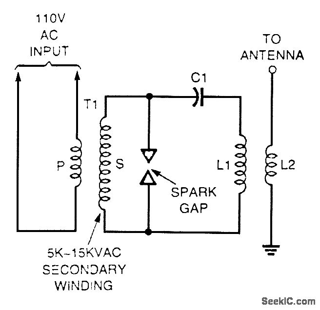
A high-voltage current-limiting transformer (T1) provides power to a basic LC tuned circuit. As capacitor C1 charges to approach the maximum output voltage of the transformer, the air gap in the spark gap breaks down, thereby completing the circuit...
A crystal oscillator circuit is composed of several gates. Figure (A) illustrates a crystal oscillator circuit operating at 1 MHz, while Figure (B) depicts a 20 MHz crystal oscillator circuit. Figure (C) represents a variable crystal oscillator circuit with...
The CD-ROM 48X RF AMP Chip serves as an RF pre-signal processor, handling signals from the optical pick-up. This chip processes the primary signal through a summing amplifier, an automatic gain control (AGC) block, and an equalization (EQ) block,...
The Pierce-gate oscillator of Figure 1 is well recognized by most designers, but few understand how to specify the crystal correctly. The crystal used in the topology of Figure 1 can be either a fundamental AT-CUT or BT-CUT. A...