
oscillator mcpos400 plus
The UHF oscillator circuit is constructed around the Mini-Circuits POS-400+ voltage-controlled oscillator chip, which is known for its reliability in generating high-frequency sine wave signals. The circuit design involves careful consideration of the power supply requirements, ensuring that both a fixed and a variable voltage can be obtained from a single source. The fixed voltage is supplied directly to pin 1 of the oscillator, while the variable voltage is managed through a potentiometer connected to pin 8.
The use of a potentiometer allows for fine-tuning of the frequency output, which is critical for applications such as the Testatika Linden experiment. The circuit's layout ensures that the potentiometer can adjust the resistance dynamically, thus altering the voltage drop across it and allowing for a continuous range of frequency outputs. The inclusion of the 6.8kΩ resistor serves to protect the circuit and ensure that the current remains within the specified limits for the POS-400+ chip, thereby preventing potential damage and ensuring stable operation.
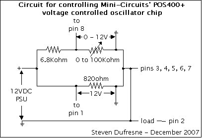
The design is further enhanced by the careful selection of the 820Ω resistor, which limits the current effectively while allowing the circuit to function within its intended parameters. The overall configuration demonstrates a practical application of basic electronic principles, such as voltage division and the use of variable resistors, to achieve a sophisticated output suitable for experimental applications. The circuit is expected to provide reliable performance across the intended frequency range, making it a valuable tool for experimentation in high-frequency applications.This is a UHF oscillator circuit I designed to make use of the Mini-Circuits POS-400+ voltage controlled oscillator chip. By giving it a voltage from 0 to 12V on pin 8 it gives out a sine wave ranging from 200MHz to 380MHz on pin 2, though my testing with a lecher line gave a range of 200MHz to 440MHz.
The purpose was to use it as a frequency sour ce for the testatika Linden experiment under the assumption that the experiment`s long wire is a lecher line that is 1 metre long, the wavelength corresponding to 300MHz which in turn corresponds to the speed of light (approximately 300, 000, 000 metres/second. ) Basically I needed two 12VDC sources, one fixed at 12V for feeding pin 1 and one that could vary between 0 and 12V for feeding pin 8, the latter for selecting the frequency (from 200MHz to 380MHz.
) Unfortunately I didn`t have two 12VDC sources where one leg of each was connected to ground. I had a power supply that I`d built where that was the case but everything else I had had both legs floating as far as I could tell. So somehow I had to come up with a circuit that would allow my one power supply to provide both fixed 12VDC and variable 12VDC.
I came up with the following circuit. It uses the fact that a single 12VDC source can be made into two separate ones by use of two parallel lines (the top and bottom horizontal lines connected to the positive leg in the above), the voltage supplied to both being 12V but the current being divided, which I didn`t care about since I had enough current. For the variable line I used the fact that voltage drops across a resistor, the bigger the resistance the bigger the voltage drop.
Since I needed various voltages I used a potentiometer for the resistor (a potentiometer is a variable resistor. ) That way I could choose the size of the voltage drop, and hence the frequency, by simply turning the potentiometer knob.
I put a 6. 8Kohm resistor in series with the potentiometer for the case where the potentiometer was turned all the way down to 0ohms. I`d need some resistance remaining on the top 12V line so I chose a 6. 8Kohm resistor. I wanted it big so that it would be big in comparison to the bottom line`s resistance, 820ohms. The specifications for the POS400+ chip requested that maximum current be 20mA. At first I had a 100ohm resistor instead of the 820ohm but the when the potentiometer was turn up all the way, the current through the 100ohm was too large so I tried 820ohms and it worked fine to limit the current to something close to but not above 20mA.
🔗 External reference
Related Circuits

An oscillator is an electronic circuit that converts energy from a direct-current source into a periodically varying electric output. An oscillator is a fundamental component in various electronic systems, serving the purpose of generating oscillating signals, typically in the form...
This quartz crystal oscillator circuit exhibits greater stability compared to a parallel resonance circuit. It is capable of generating frequencies up to 30 MHz or even higher when utilizing BFR91 transistors for T1 and T2, along with reduced values...
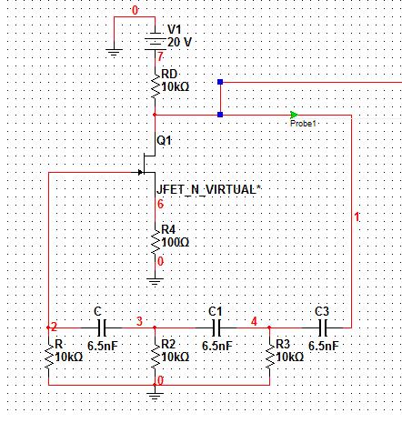
Assistance is required for the design of a FET-based Wien bridge oscillator and its simulation using PSpice. Any suggestions would be appreciated. The Wien bridge oscillator is a type of electronic oscillator that generates sine waves. It employs a bridge...
Its most useful application is as a signal injector for radios and TVs. A square wave is the most suitable for testing the intermediate frequency (IF) strip as the signal will pass through the IF transformers without any attenuation,...
This generally results in a square wave if the frequency of oscillation is low enough relative to the amplifier's bandwidth. The schematic of a crystal-controlled oscillator features a low-frequency sine wave oscillator characterized by low distortion, wideband operation, and...
Hand and body motions in proximity to the sensing antennas produce frequency changes in a Hartley oscillator operating at approximately 750kHz. The signal from this variable oscillator is mixed with a constant reference frequency in a ring modulator and...
Warning: include(partials/cookie-banner.php): Failed to open stream: Permission denied in /var/www/html/nextgr/view-circuit.php on line 713
Warning: include(): Failed opening 'partials/cookie-banner.php' for inclusion (include_path='.:/usr/share/php') in /var/www/html/nextgr/view-circuit.php on line 713