
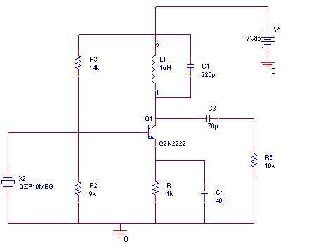
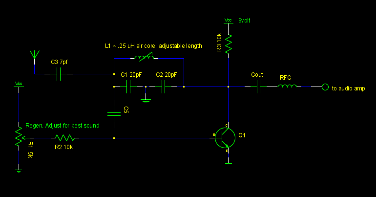
variable Hartley oscillator
The circuit operates based on the detection of hand and body motions near the sensing antennas, which influence the frequency of a Hartley oscillator tuned to approximately 750 kHz. This oscillator generates a variable frequency signal that is mixed with a constant reference frequency in a ring modulator. The output from the ring modulator is then processed through a low-pass filter, which effectively isolates the difference between the variable and reference frequencies, ensuring that only the desired signal is retained for further processing.
The design incorporates duplicate sensing circuitry for both pitch and volume control, allowing for independent manipulation of each parameter. The output from the ring modulators is amplified using discrete transistor amplifiers, which also contribute additional low-pass filtering due to feedback capacitors connected from the collector to the base. This configuration enhances the stability and fidelity of the output signals.
The pitch sensing circuitry produces a sine wave output that is directed to a Voltage Controlled Amplifier (VCA) for volume processing. To convert the fully filtered sine wave signal into a square wave, a Schmitt trigger is employed. This square wave is then differentiated to create narrow pulses, which are subsequently integrated to generate control voltages. The Volume Control Voltage derived from this process acts as the control signal for the internal VCA.
The front panel includes a "Timbre" control that allows the user to blend sine and square wave inputs into the VCA. The VCA itself is constructed from discrete transistors and a single-stage operational amplifier, with gain structures designed to induce distortion at maximum volume settings, adding a dynamic character to the audio output.
Moreover, the Volume Control Voltage is further differentiated to yield a Velocity Control Voltage, which is routed to the differential amplifier input of the VCA. This arrangement facilitates asymmetrical distortion effects in response to rapid changes in volume, enhancing the expressive capabilities of the device. The Velocity Control Voltage is also processed through another Schmitt trigger, generating gate and S-trigger outputs, which can be utilized for additional control functions or interfacing with other devices in a modular setup.Hand and body motions in proximity to the sensing antennas produce frequency changes in a Hartley oscillator operating at approximately 750kHz. The signal from this variable oscillator is mixed with a constant reference frequency in a ring modulator and the result passed through a single pole of low pass filter to leave only the difference between the variable and reference oscillator frequencies.
The sensing circuitry is duplicated for Pitch and Volume sensor antennas. The output of the ring modulators is boosted in level by discrete transistor amps which also provide a second pole of low pass filtering because of the the feedback capacitors from collector to base. The sine wave output of the pitch sensing circuitry is routed to the VCA () for volume processing. The fully filtered signal is converted to a square wave by a Schmitt trigger, then differentiated to produce narrow pulses which are integrated to produce control voltages. The Volume Control Voltage is used as the control signal for the internal VCA. The front panel "Timbre" control allows a blend of sine and/or square wave to serve as the input to the VCA which consists of discrete transistors and a single stage opamp.
VCA gain structures are arranged so the stage will distort when Volume is set to max. The Volume Control Voltage is differentiated to produce a Velocity Control Voltage. Velocity CV is also routed to the diff. amp input of the VCA to produce asymmetrical distortions in response to rapid volume changes. (see Panel Controls). The Velocity CV is thresholded by a Schmitt trigger to produce a gate and S-trigger outputs. 🔗 External reference
Related Circuits
A simulation of a 27 MHz transmitter circuit is to be conducted using PSPICE. The circuit diagram is provided as Figure 1 in the following content. The 27 MHz transmitter circuit typically consists of several key components, including an oscillator,...

Edwin Henry Colpitts was a communications pioneer best known for his invention of the Colpitts oscillator. As research branch chief for Western Electric in the early 1900s, he and scientists under his direction achieved significant advances in the development...
A truly timeless circuit. The LM317 is a versatile and highly efficient 1.2-37V voltage regulator that can provide up to 1.5A of current with a large heat sink. It is ideal for just about any application. This was the...
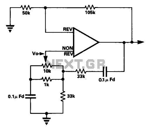
In the circuit, the frequency trimming component is configured such that the voltage across it is in quadrature with the voltage V0 from the bridge. This arrangement allows for adjustments to be made with minimal changes to the attenuation...
The circuit is a modified Colpitts oscillator, tuned with MV209 varactor diodes. The resonating inductor and the drain choke are selected by a rotary switch. 1N5711 Schottky diode, D, clamps the maximum positive voltage on the gate of oscillator...
A common emitter Colpitts oscillator was constructed using variable capacitors for C1 and C2, and a few turns of wire wrapped around a pencil for the inductor L. Resistors R1 and R2 were replaced with a trimmer potentiometer to...
Warning: include(partials/cookie-banner.php): Failed to open stream: Permission denied in /var/www/html/nextgr/view-circuit.php on line 713
Warning: include(): Failed opening 'partials/cookie-banner.php' for inclusion (include_path='.:/usr/share/php') in /var/www/html/nextgr/view-circuit.php on line 713