
Quartz Crystal Oscillator Circuit

The quartz crystal oscillator circuit operates on the principle of resonance, utilizing a quartz crystal to maintain a precise frequency output. The stability of this circuit is significantly enhanced due to the inherent properties of the quartz crystal, which provides a stable frequency reference that is less susceptible to variations in temperature and load conditions.
In this design, the transistors T1 and T2, specifically the BFR91 model, are configured in a feedback loop to amplify the oscillation generated by the crystal. The resistors R1 and R2 are critical in setting the gain of the circuit; by reducing their values, the overall gain can be increased, allowing the circuit to achieve higher frequency outputs beyond the standard 30 MHz threshold.
The inclusion of a MOSFET buffer in the circuit design is crucial for isolating the oscillator from external influences. This buffer stage prevents loading effects from subsequent stages or connected circuits that could otherwise dampen the oscillation or introduce noise. The MOSFET, known for its high input impedance, ensures that the oscillator's performance remains unaffected by the variations in the connected load.
For optimal performance, careful selection of the crystal frequency, transistor parameters, and resistor values is essential. Additionally, the layout of the circuit should minimize parasitic capacitance and inductance, which can degrade signal integrity at higher frequencies. This oscillator circuit is suitable for applications requiring precise frequency generation, including communication systems, clock generation, and signal processing tasks.This quartz crystal oscillator circuit has greater stability than a parallel resonance circuit. It generates frequencies up to 30 MHz or even higher if you use BFR91 for T1, T2 transistors and reduce R1 R2 values. The MOSFET buffer insulate the oscillator from any connected circuit. 🔗 External reference
Related Circuits
The LM4844 is an integrated audio subsystem designed for stereo cell phone applications. Operating on a 3.3V supply, it combines a stereo speaker amplifier delivering 495mW per channel into an 8Ω load and a stereo OCL headphone amplifier delivering...
This capacitance meter circuit is similar to previous meter circuits, but it utilizes transistors instead of logic gates. A schematic diagram is provided. The capacitance meter circuit operates by measuring the capacitance of a capacitor through a time-based method. The...
The circuit depicted in the figure is a highly technical OTL (Output Transformer-Less) amplifier circuit. It features a frequency response range of 10 Hz to 100 kHz and exhibits a total harmonic distortion of less than 0.1%, which is...
This is a straightforward liquid detector that utilizes a relay to activate an evacuation mechanism. It can be employed for water or any liquid that conducts electricity. Any PNP transistor capable of handling the relay current can be used....
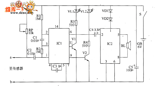
The bearing fault detection circuit comprises bearing detection sensors, a signal processing circuit, and a sound and light circuit. The signal processing circuit includes the input socket XS, a voice integrated circuit IC1, capacitors C1 to C3, resistors R1,...
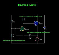
This is a flashing lamp circuit. This circuit operates with a 6V power supply. It can be installed on a bicycle or a car. A common transistor, the 2N3904, is used in this circuit. The flashing lamp circuit is designed...